A165E-M-02 Omron, A165E-M-02 Datasheet - Page 201
A165E-M-02
Manufacturer Part Number
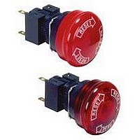
A165E-M-02
Description
SWITCH, EMERGENCY STOP, DPST-NC, 250VAC
Manufacturer
Omron
Series
A165Er
Datasheets
1.M2DA-7001.pdf
(265 pages)
2.A165E-S-02.pdf
(10 pages)
3.A165E-02.pdf
(17 pages)
4.A165E-M-02.pdf
(9 pages)
Specifications of A165E-M-02
Contact Configuration
DPST-NC
Switch Operation
Pushlock Turn Reset
Contact Voltage Ac Nom
250V
Contact Voltage Dc Nom
30V
Contact Current Max
5A
Actuator Style
Round
Switch Terminals
Solder
Actuator Length
20mm
Ip Rating
IP65
Pole Throw Configuration
DPST
Switch Function Configuration
N.C.
Current Rating (max)
5A
Operating Temp Range
-10C to 55C
Contact Form
DPST - NC
Actuator Diameter
40mm
Svhc
No SVHC
Rohs Compliant
Yes
Lead Free Status / RoHS Status
Lead free / RoHS Compliant
Lead Free Status / RoHS Status
Lead free / RoHS Compliant, Lead free / RoHS Compliant


Move the lever in the direction indicated by the arrow in the following
figure, then pull the Operation Unit or the Switch Blocks.
Since the lever has a hole with an inside diameter of 6.5 mm, the
lever can be moved in the specified direction by inserting a screw-
driver into the hole and then moving the screwdriver.
Emergency Stop Switch
Insert the protrusion of the Tightening Wrench (A22Z-3905) into the
Cap slot and then turn to remove the Cap.
Installing/Replacing from the Panel
Surface
Insert the Lamp Extractor (A22Z-3901) into the lamp, then rotate the
Extractor while pressing it.
Installing/Replacing on the Switch
Grip the indicator with your fingers, then rotate the indicator while
pressing it against the Switch.
Assembling the Cap
Installing/Replacing the Lamp
Screwdriver
Mounting the Switch
The Standard-size Legend Plate Frame can be mounted. Mount the
Frame as shown in the following diagram. Mount the Switch in the
same way as for an ordinary panel.
Creating a Cable Port Hole
Place the tip of a screwdriver on the surface where the cable port
hole is to be created with the cover attached and strike the screw-
driver to punch a hole. Attempts to punch a hole on the other side of
the case will damage the Box.
Securing the Connector Cable
1. Insert the connector into the cable port hole in the Box and secure
2. Open a hole in the thin rubber section of the rubber ring.
3. Pass the tightening cap through the cable, insert the cable into
7 to 9 dia.
9 to 11 dia.
with the fixing nut inside the box.
the connector, and tighten the hexagonal nut to secure the cable.
Lock nut
Control Box (Enclosure)
Cable diameter
Inside
Box
Outside
Rubber washer
Connector
A22Z-3500-1
A22Z-3500-2
Snap-in Legend Plate
Tightening cap
Connector
Cable
199
Related parts for A165E-M-02
Image
Part Number
Description
Manufacturer
Datasheet
Request
R

Part Number:
Description:
ESTOP OPERATOR
Manufacturer:
Omron
Datasheet:
Part Number:
Description:
E-stop,non-lighted,1NC,40diamt
Manufacturer:
Omron
Datasheet:

Part Number:
Description:
E-stop,non-lighted,40diameter
Manufacturer:
Omron
Datasheet:
Part Number:
Description:
ESTOP OPERATOR
Manufacturer:
Omron
Datasheet:
Part Number:
Description:
1 NC CONTACT
Manufacturer:
Omron
Datasheet:

Part Number:
Description:
2 NC CONTACTS
Manufacturer:
Omron
Datasheet:
Part Number:
Description:
2 NC CONTACTS
Manufacturer:
Omron
Datasheet:
Part Number:
Description:
ESTOP OPERATOR
Manufacturer:
Omron
Datasheet:
Part Number:
Description:
E-stop,lighted,1NC,40diameter
Manufacturer:
Omron
Datasheet:
Part Number:
Description:
E-stop,lighted,2NC,40diameter
Manufacturer:
Omron
Datasheet:

Part Number:
Description:
SWITCH PB SQUARE MOM SPDT GREEN
Manufacturer:
Omron
Datasheet:
Part Number:
Description:
SWITCH PB SQUARE MOM SPDT WHITE
Manufacturer:
Omron
Datasheet:
Part Number:
Description:
SWITCH PB SQUARE MOM SPDT YELLOW
Manufacturer:
Omron
Datasheet:
Part Number:
Description:
SWITCH PB RECTANG MOM SPDT BLUE
Manufacturer:
Omron
Datasheet:
Part Number:
Description:
SWITCH PB RECTANG MOM SPDT YEL
Manufacturer:
Omron
Datasheet: