A165E-M-02 Omron, A165E-M-02 Datasheet - Page 132
A165E-M-02
Manufacturer Part Number
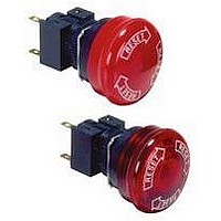
A165E-M-02
Description
SWITCH, EMERGENCY STOP, DPST-NC, 250VAC
Manufacturer
Omron
Series
A165Er
Datasheets
1.M2DA-7001.pdf
(265 pages)
2.A165E-S-02.pdf
(10 pages)
3.A165E-02.pdf
(17 pages)
4.A165E-M-02.pdf
(9 pages)
Specifications of A165E-M-02
Contact Configuration
DPST-NC
Switch Operation
Pushlock Turn Reset
Contact Voltage Ac Nom
250V
Contact Voltage Dc Nom
30V
Contact Current Max
5A
Actuator Style
Round
Switch Terminals
Solder
Actuator Length
20mm
Ip Rating
IP65
Pole Throw Configuration
DPST
Switch Function Configuration
N.C.
Current Rating (max)
5A
Operating Temp Range
-10C to 55C
Contact Form
DPST - NC
Actuator Diameter
40mm
Svhc
No SVHC
Rohs Compliant
Yes
Lead Free Status / RoHS Status
Lead free / RoHS Compliant
Lead Free Status / RoHS Status
Lead free / RoHS Compliant, Lead free / RoHS Compliant


Precautions
Refer to the Technical Information for Pushbutton Switches (Cat. No. A143) and the Precautions section for the A16.
Mounting
When mounting the Case onto the Socket Unit, ensure that the orien-
tation is correct. Perform mounting with the • mark on the Case and
the TOP mark on the Socket Unit facing in the same direction.
130
Cat. No. A127-E1-03
Correct Use
Case
ALL DIMENSIONS SHOWN ARE IN MILLIMETERS.
To convert millimeters into inches, multiply by 0.03937. To convert grams into ounces, multiply by 0.03527.
mark
In the interest of product improvement, specifications are subject to change without notice.
Socket Unit
TOP mark
Wiring
When using stranded wire, gather the ends of the strands together
before wiring.
When wiring, insert the wire until it comes into contact with some-
thing. After wiring is completed, pull on the wires to confirm that they
are connected securely.
After wiring, ensure that continuous pressure is not applied to the ter-
minals.
Refer to internal connections diagrams and confirm the terminal
numbers before performing wiring.
Screw-Less Clamps
Mounting Procedure
1. Strip a length of 10 mm off the end of the wire (allowable range:
2. Bunch wire strands together and straighten them.
3. Insert the wire into the insertion hole while pressing the release
4. Let go of the release button to lock the wire into place.
5. After locking, pull on the wire gently to confirm that it is securely
Removing Procedure
Remove wires by pulling them while pressing the release button.
Note: When reusing wires that have already been locked, cut off the
10 1 mm).
button at the side of the hole. (Using a precision screwdriver is
recommended.)
locked.
end of the wire and strip the wire again before using.
Related parts for A165E-M-02
Image
Part Number
Description
Manufacturer
Datasheet
Request
R

Part Number:
Description:
ESTOP OPERATOR
Manufacturer:
Omron
Datasheet:
Part Number:
Description:
E-stop,non-lighted,1NC,40diamt
Manufacturer:
Omron
Datasheet:

Part Number:
Description:
E-stop,non-lighted,40diameter
Manufacturer:
Omron
Datasheet:
Part Number:
Description:
ESTOP OPERATOR
Manufacturer:
Omron
Datasheet:
Part Number:
Description:
1 NC CONTACT
Manufacturer:
Omron
Datasheet:

Part Number:
Description:
2 NC CONTACTS
Manufacturer:
Omron
Datasheet:
Part Number:
Description:
2 NC CONTACTS
Manufacturer:
Omron
Datasheet:
Part Number:
Description:
ESTOP OPERATOR
Manufacturer:
Omron
Datasheet:
Part Number:
Description:
E-stop,lighted,1NC,40diameter
Manufacturer:
Omron
Datasheet:
Part Number:
Description:
E-stop,lighted,2NC,40diameter
Manufacturer:
Omron
Datasheet:

Part Number:
Description:
SWITCH PB SQUARE MOM SPDT GREEN
Manufacturer:
Omron
Datasheet:
Part Number:
Description:
SWITCH PB SQUARE MOM SPDT WHITE
Manufacturer:
Omron
Datasheet:
Part Number:
Description:
SWITCH PB SQUARE MOM SPDT YELLOW
Manufacturer:
Omron
Datasheet:
Part Number:
Description:
SWITCH PB RECTANG MOM SPDT BLUE
Manufacturer:
Omron
Datasheet:
Part Number:
Description:
SWITCH PB RECTANG MOM SPDT YEL
Manufacturer:
Omron
Datasheet: