GCM1555C1H221JA16D Murata, GCM1555C1H221JA16D Datasheet - Page 46
GCM1555C1H221JA16D
Manufacturer Part Number
GCM1555C1H221JA16D
Description
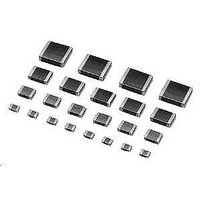
Multilayer Ceramic Capacitors (MLCC) - SMD/SMT 0402 220pF 50volts C0G +/-5%
Manufacturer
Murata
Series
GCMr
Datasheets
1.GCM188R71C105KA64D.pdf
(50 pages)
2.GCM1555C1H221JA16D.pdf
(2 pages)
3.GCM1555C1H221JA16D.pdf
(1 pages)
Specifications of GCM1555C1H221JA16D
Voltage Rating
50 Volts
Operating Temperature Range
- 55 C to + 125 C
Temperature Coefficient / Code
C0G (NP0)
Product
Automotive MLCCs
Dimensions
0.5 mm W x 1 mm L x 0.5 mm H
Dissipation Factor Df
0.01
Termination Style
SMD/SMT
Capacitance
220 pF
Tolerance
5 %
Package / Case
0402 (1005 metric)
Lead Free Status / RoHS Status
Lead free / RoHS Compliant
Available stocks
Company
Part Number
Manufacturer
Quantity
Price
Company:

Part Number:
GCM1555C1H221JA16D
Manufacturer:
MURATA
Quantity:
640 000


2
!Note
• This PDF catalog is downloaded from the website of Murata Manufacturing co., ltd. Therefore, it’s specifications are subject to change or our products in it may be discontinued without advance notice. Please check with our
• This PDF catalog has only typical specifications because there is no space for detailed specifications. Therefore, please approve our product specifications or transact the approval sheet for product specifications before ordering.
sales representatives or product engineers before ordering.
1. Construction of Board Pattern
Construction and Dimensions of Pattern (Example)
Land Layout to Prevent Excessive Solder
!Note
44
Notice
Examples of
Prohibition
Examples of
Improvements
by the Land
Division
Solder and Mounting
After installing chips, if solder is excessively applied to
the circuit board, mechanical stress will cause destruction
resistance characteristics to lower. To prevent this, be
extremely careful in determining shape and dimension
before designing the circuit board diagram.
• Please read rating and !CAUTION (for storage, operating, rating, soldering, mounting and handling) in this catalog to prevent smoking and/or burning, etc.
• This catalog has only typical specifications because there is no space for detailed specifications. Therefore, please approve our product specifications or transact the approval sheet for product specifications before ordering.
Chip Capacitor
Preparing slit helps flux
cleaning and resin coating on
the back of the capacitor.
c
b
d
a
e
Solder Resist
Mounting Close to a Chassis
Slit
d
d
1
Chassis
2
Solder Resist
Land
Land Pattern
Base board
Solder (Ground solder)
d
1
<d
Adhesive
2
L
in section
in section
W
Flow Soldering
Flow soldering : 3.2g1.6 or less available.
Reflow Soldering
3.2g1.6
3.2g2.5
2.0g1.25
3.2g1.6
2.0g1.25
Mounting with Leaded Components
LgW
LgW
Solder Resist
1.0-1.2
2.2-2.6
1.0-1.2
2.2-2.4
2.0-2.4
a
a
Lead Wire Connected
to a Part Provided
with Lead Wires.
0.9-1.0
1.0-1.1
0.6-0.7
0.8-0.9
1.0-1.2
in section
in section
b
b
0.8-1.1
1.0-1.4
0.8-1.1
1.0-1.4
1.8-2.3
c
c
Mounting Leaded Components Later
Continued on the following page.
Solder Resist
1.0-2.0
1.0-2.0
d
-
3.2-3.7
4.1-4.6
Soldering Iron
Lead Wire of
Component to be
Connected Later.
(in mm)
e
-
in section
in section
C03E.pdf
09.3.31
Related parts for GCM1555C1H221JA16D
Image
Part Number
Description
Manufacturer
Datasheet
Request
R

Part Number:
Description:
Murata Microblower 20x20 DCDC Driver Board - Samples Only
Manufacturer:
Murata
Part Number:
Description:
357-036-542-201 CARDEDGE 36POS DL .156 BLK LOPRO
Manufacturer:
Murata
Datasheet:
Part Number:
Description:
Manufacturer:
Murata
Datasheet:
Part Number:
Description:
Manufacturer:
Murata
Datasheet:
Part Number:
Description:
Manufacturer:
Murata
Datasheet:
Part Number:
Description:
Manufacturer:
Murata
Datasheet:
Part Number:
Description:
Manufacturer:
Murata
Datasheet:
Part Number:
Description:
Manufacturer:
Murata
Datasheet:
Part Number:
Description:
Manufacturer:
Murata
Datasheet:
Part Number:
Description:
BLM21BD751SN1On-Board Type (DC) EMI Suppression Filters
Manufacturer:
Murata
Datasheet:
Part Number:
Description:
BLM15AG100SN1On-Board Type (DC) EMI Suppression Filters
Manufacturer:
Murata
Datasheet:
Part Number:
Description:
NFE31PT222Z1E9On-Board Type (DC) EMI Suppression Filters
Manufacturer:
Murata
Datasheet:
Part Number:
Description:
Chip Coil
Manufacturer:
Murata
Datasheet:
Part Number:
Description:
Chip Coil
Manufacturer:
Murata
Datasheet: