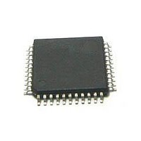
MC56F8255VLD Freescale Semiconductor, MC56F8255VLD Datasheet - Page 38

MC56F8255VLD
Manufacturer Part Number
MC56F8255VLD
Description
DSC 64K FLASH 60MHZ 44-LQFP
Manufacturer
Freescale Semiconductor
Series
56F8xxxr
Datasheets
1.TWR-56F8257.pdf
(88 pages)
2.MC56F8245VLD.pdf
(14 pages)
3.MC56F8245VLD.pdf
(2 pages)
4.MC56F8245VLD.pdf
(629 pages)
Specifications of MC56F8255VLD
Core Processor
56800E
Core Size
16-Bit
Speed
60MHz
Connectivity
CAN, I²C, LIN, SCI, SPI
Peripherals
LVD, POR, PWM, WDT
Number Of I /o
35
Program Memory Size
64KB (32K x 16)
Program Memory Type
FLASH
Ram Size
4K x 16
Voltage - Supply (vcc/vdd)
3 V ~ 3.6 V
Data Converters
A/D 8x12b, D/A 1x12b
Oscillator Type
Internal
Operating Temperature
-40°C ~ 105°C
Package / Case
44-LQFP
Product
DSCs
Processor Series
56800E
Core
56800E
Device Million Instructions Per Second
60 MIPs
Maximum Clock Frequency
60 MHz
Number Of Programmable I/os
35
Data Ram Size
8 KB
Operating Supply Voltage
3.3 V
Maximum Operating Temperature
+ 105 C
Mounting Style
SMD/SMT
Minimum Operating Temperature
- 40 C
On-chip Adc
12 bit, 4 Channel
Lead Free Status / RoHS Status
Lead free / RoHS Compliant
Eeprom Size
-
Lead Free Status / Rohs Status
Details
Available stocks
Company
Part Number
Manufacturer
Quantity
Price
Company:
Part Number:
MC56F8255VLD
Manufacturer:
Freescale Semiconductor
Quantity:
10 000
General System Control Information
when selecting a crystal, because crystal parameters determine the component values required to provide maximum stability
and reliable startup. The load capacitance values used in the oscillator circuit design should include all stray layout capacitances.
The crystal and associated components should be mounted as near as possible to the EXTAL and XTAL pins to minimize output
distortion and startup stabilization time. When using low-frequency, low-power mode, the only external component is the
crystal itself. In the other oscillator modes, load capacitors (C
resistor (R
5.4.3
The recommended method of connecting an external clock appears in
CLKIN pin while:
The external clock input must be generated using a relatively low-impedance driver with a maximum frequency not greater than
120 MHz.
38
•
•
both the EXT_SEL bit and the CLK_MODE bit in the OSCTL register are set, and
corresponding bits in the GPIOB_PER register in the GPIO module and the GPS_C0 bit in the GPS0 register in the
system integration module (SIM) are set to the correct values.
S
) may be used in high-gain modes. Recommended component values appear in
Figure 9. Typical Crystal Oscillator Circuit without Frequency Compensation Capacitor
Crystal Frequency = 4–16 MHz
OSC_DIV2 = 1 if 16 MHz is chosen
Alternate External Clock Input
Crystal Frequency = 4–16 MHz
OSC_DIV2 = 1 if 16 MHz is chosen
Figure 10. Typical Crystal or Ceramic Resonator Circuit
MC56F825x/MC56F824x Digital Signal Controller, Rev. 3
C
1
XTAL
XTAL
MC56F825x/MC56F824x
MC56F825x/MC56F824x
x
, C
y
) and feedback resistor (R
Figure
R
F
11. The external clock source is connected to the
EXTAL
EXTAL
C
2
F
Table
) are required. In addition, a series
27.
Freescale Semiconductor


