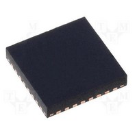
MAX5978ETJ+ Maxim Integrated Products, MAX5978ETJ+ Datasheet - Page 34

MAX5978ETJ+
Manufacturer Part Number
MAX5978ETJ+
Description
Hot Swap & Power Distribution 0-16V HOTSWAP CONTLR W/10BIT CUR VOLT MON
Manufacturer
Maxim Integrated Products
Datasheet
1.MAX5978ETJ.pdf
(38 pages)
Specifications of MAX5978ETJ+
Product
Controllers & Switches
Supply Voltage (max)
16 V
Supply Voltage (min)
0 V
Power Dissipation
2759 mW
Operating Temperature Range
- 40 C to + 85 C
Mounting Style
SMD/SMT
Supply Current
2.5 mA
Package / Case
TQFN-32
Lead Free Status / RoHS Status
Lead free / RoHS Compliant
0 to 16V, Hot-Swap Controller with 10-Bit
Current, Voltage Monitor, and 4 LED Drivers
Table 53. Device Slave Address Settings
Figure 5. Bit Transfer
Each clock pulse transfers 1 data bit. The data on SDA
must remain stable while SCL is high (see Figure 5); oth-
erwise, the device registers a START or STOP condition
(see Figure 6) from the master. SDA and SCL idle high
when the bus is not busy.
Both SCL and SDA idle high when the bus is not busy.
A master device signals the beginning of a transmission
with a START condition (see Figure 3) by transitioning
SDA from high to low while SCL is high. The master
device issues a STOP condition (see Figure 6) by transi-
tioning SDA from low to high while SCL is high. A STOP
condition frees the bus for another transmission. The bus
remains active if a Repeated START condition is gener-
ated, such as in the block read protocol (see Figure 7).
34
ADDRESS INPUT
Open
Open
Open
High
High
High
Low
Low
Low
A1
SDA
SCL
STATE
DATA LINE STABLE,
DATA VALID
Open
Open
Open
High
High
High
Low
Low
Low
A0
ADDR 7
DATA ALLOWED
CHANGE OF
0
0
0
0
0
0
0
0
0
START and STOP Conditions
ADDR 6
1
1
1
1
1
1
1
1
1
Bit Transfer
ADDR 5
1
1
1
1
1
1
1
1
1
ADDR 4
I
2
C ADDRESS BITS
Figure 6. START and STOP Conditions
The device recognizes a STOP condition at any point
during transmission except if a STOP condition occurs in
the same high pulse as a START condition. This condi-
tion is not a legal I
must separate any START and STOP condition.
A Repeated START (SR) condition may indicate a change
of data direction on the bus. Such a change occurs when
a command word is required to initiate a read operation
(see Figure 4). SR may also be used when the bus mas-
ter is writing to several I
relinquish control of the bus. The device serial interface
supports continuous write operations with or without an
SR condition separating them. Continuous read opera-
tions require SR conditions because of the change in
direction of data flow.
1
1
1
0
0
0
0
0
0
SDA
SCL
CONDITION
START
S
ADDR 3
0
0
0
1
1
1
0
0
0
2
C format. At least one clock pulse
ADDR 2
2
C devices and does not want to
1
0
0
1
0
0
1
0
0
Repeated START Conditions
Early STOP Conditions
ADDR 1
0
1
0
0
1
0
0
1
0
ADDR 0
CONDITION
R/W
R/W
R/W
R/W
R/W
R/W
R/W
R/W
R/W
STOP
P


