AT88RF1354-ZU Atmel, AT88RF1354-ZU Datasheet - Page 42
AT88RF1354-ZU
Manufacturer Part Number
AT88RF1354-ZU
Description
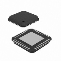
IC RF READER 13.56MHZ 36-VQFN
Manufacturer
Atmel
Datasheet
1.AT88RF1354-ZU.pdf
(48 pages)
Specifications of AT88RF1354-ZU
Frequency
13.56MHz
Features
ISO14443-B
Package / Case
36-VQFN Exposed Pad, 36-HVQFN, 36-SQFN, 36-DHVQFN
Pin Count
36
Screening Level
Industrial
Lead Free Status / RoHS Status
Lead free / RoHS Compliant
Rf Type
-
Lead Free Status / Rohs Status
Compliant


D.6.2. Site Redress
D.6.3. Solder Paste Printing
D.6.4. Component Placement
D.6.5. Component Attachment
D.7.
D.8.
42
After the component has been removed, the site needs to be cleaned properly. It is best to use a combination of a
blade-style conductive tool and a desoldering braid. The width of the blade should be matched to the maximum width of
the footprint and the blade temperature should be low enough not to cause any damage to the circuit board. Once the
residual solder has been removed, the lands should be cleaned with a solvent. The solvent is usually specific to the
type of paste used in the original assembly and the paste manufacturer’s recommendations should be followed.
Because of their small size and the fine pitches, solder paste deposition for the QFNs requires extra care. However, a
uniform and precise deposition can be achieved if a miniature stencil specific to the component is used. The stencil
aperture should be aligned with the pads under 50 to 100X magnification. The stencil should then be lowered onto the
PCB and the paste should be deposited with a small metal squeegee blade. Alternatively, the mini stencil can be used
to print paste on the package side. A 125 microns thick stencil with the aperture size and shape same as the package
land should be used. Also, no-clean flux should be used, as small standoff of the QFNs does not leave much room for
cleaning.
QFN packages are expected to have superior self-centering ability due to their small mass and the placement of this
package should be similar to that of BGAs. As the leads are on the underside of the package, a split-beam optical
system should be used to align the component on the board. This will form an image of leads overlaid on the mating
footprint and aid in proper alignment. Again, the alignment should be done at 50 to 100X magnification. The placement
machine should have the capability of allowing fine adjustments in the X, Y, and the rotational axes.
The reflow profile developed during original attachment or removal should be used to attach the new component.
Since all reflow profile parameters have already been optimized, using the same profile will eliminate the need for
thermocouple feedback and will reduce operator dependencies.
Successful use of the AT88RF1354 QFN package requires careful development of the PCB and the manufacturing
process. This appendix contains guidelines to assist the design and manufacturing engineers in optimizing the PC
board and processes. These guidelines include:
Disclaimer
These are only general guidelines Atmel received from its package vendor. Atmel does not make direct
recommendation for board design nor does it take legal liability and responsibility for the information in this appendix.
Please refer to the IPC website for more information regarding board design and processing.
13.56 MHz Type B RF Reader Specification
Summary
─ PCB thermal pad sized to match the package thermal pad.
─ 1 ounce copper thickness on all layers for optimum heat transfer.
─ Nine or more thermal vias in the PCB thermal pad for heat transfer.
─ SMD solder masking of thermal pad.
─ NSMD solder masking of pads for package pins.
─ 50 to 75 micron solder joint standoff height.
─ Laser-cut, electro-polished 0.125 mm stainless steel stencil.
─ No Clean, Type 3 solder paste.
─ Hot gas rework process.
8547B–RFID–3/09
Related parts for AT88RF1354-ZU
Image
Part Number
Description
Manufacturer
Datasheet
Request
R

Part Number:
Description:
DEV KIT FOR AVR/AVR32
Manufacturer:
Atmel
Datasheet:

Part Number:
Description:
INTERVAL AND WIPE/WASH WIPER CONTROL IC WITH DELAY
Manufacturer:
ATMEL Corporation
Datasheet:
Part Number:
Description:
Low-Voltage Voice-Switched IC for Hands-Free Operation
Manufacturer:
ATMEL Corporation
Datasheet:
Part Number:
Description:
MONOLITHIC INTEGRATED FEATUREPHONE CIRCUIT
Manufacturer:
ATMEL Corporation
Datasheet:
Part Number:
Description:
AM-FM Receiver IC U4255BM-M
Manufacturer:
ATMEL Corporation
Datasheet:
Part Number:
Description:
Monolithic Integrated Feature Phone Circuit
Manufacturer:
ATMEL Corporation
Datasheet:
Part Number:
Description:
Multistandard Video-IF and Quasi Parallel Sound Processing
Manufacturer:
ATMEL Corporation
Datasheet:
Part Number:
Description:
High-performance EE PLD
Manufacturer:
ATMEL Corporation
Datasheet:
Part Number:
Description:
8-bit Flash Microcontroller
Manufacturer:
ATMEL Corporation
Datasheet:
Part Number:
Description:
2-Wire Serial EEPROM
Manufacturer:
ATMEL Corporation
Datasheet: