AT88RF1354-ZU Atmel, AT88RF1354-ZU Datasheet - Page 37
AT88RF1354-ZU
Manufacturer Part Number
AT88RF1354-ZU
Description
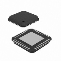
IC RF READER 13.56MHZ 36-VQFN
Manufacturer
Atmel
Datasheet
1.AT88RF1354-ZU.pdf
(48 pages)
Specifications of AT88RF1354-ZU
Frequency
13.56MHz
Features
ISO14443-B
Package / Case
36-VQFN Exposed Pad, 36-HVQFN, 36-SQFN, 36-DHVQFN
Pin Count
36
Screening Level
Industrial
Lead Free Status / RoHS Status
Lead free / RoHS Compliant
Rf Type
-
Lead Free Status / Rohs Status
Compliant


13.56 MHz Type B RF Reader Specification
Figure D-4. Solder Mask Options for Thermal Vias
Via Tenting
Via Tenting
Via Plugging
Via Encroached
from Top
from Bottom
from Bottom
from Bottom
All of these options have pros and cons when mounting the QFN package on the board. While via tenting from the top
side may result in smaller voids, the presence of the solder mask on the top side of the board may hinder proper paste
printing. On the other hand, both via tenting from bottom or via plugging from bottom may result in larger voids due to
out-gassing covering more than two vias. Finally, encroached vias allow the solder to wick inside the vias and reduce
the size of the voids. However, it also results in lower standoff of the package, which is controlled by the solder
underneath the exposed pad. Figure D-5. shows representative x-rays of QFN packages mounted on the boards with
the different via treatments.
Encroached via, depending on the board thickness and the amount of solder printed underneath the exposed pad, may
also result in solder protruding from the other side of the board. Note that the vias are not completely filled with solder,
suggesting that solder wets down the via walls until the ends are plugged. This protrusion is a function of the PCB
thickness, the amount of paste coverage in the thermal pad region, and the surface finish of the PCB. Atmel’s
experience is that this protrusion can be avoided by using a lower volume of the solder paste and reduced reflow peak
temperature. If solder protrusion cannot be avoided, the QFN components may have to be assembled on the top side
(or final pass) assembly, as the protruded solder will impede acceptable solder paste printing on the other side of the
PCB.
Figure D-5. X-ray showing Voids in Thermal Pad Solder Joint
Vias Tented
Vias Tented
Via Plugged
Via Encroached
from Top
from Bottom
from Bottom
from Bottom
37
8547B–RFID–3/09
Related parts for AT88RF1354-ZU
Image
Part Number
Description
Manufacturer
Datasheet
Request
R

Part Number:
Description:
DEV KIT FOR AVR/AVR32
Manufacturer:
Atmel
Datasheet:

Part Number:
Description:
INTERVAL AND WIPE/WASH WIPER CONTROL IC WITH DELAY
Manufacturer:
ATMEL Corporation
Datasheet:
Part Number:
Description:
Low-Voltage Voice-Switched IC for Hands-Free Operation
Manufacturer:
ATMEL Corporation
Datasheet:
Part Number:
Description:
MONOLITHIC INTEGRATED FEATUREPHONE CIRCUIT
Manufacturer:
ATMEL Corporation
Datasheet:
Part Number:
Description:
AM-FM Receiver IC U4255BM-M
Manufacturer:
ATMEL Corporation
Datasheet:
Part Number:
Description:
Monolithic Integrated Feature Phone Circuit
Manufacturer:
ATMEL Corporation
Datasheet:
Part Number:
Description:
Multistandard Video-IF and Quasi Parallel Sound Processing
Manufacturer:
ATMEL Corporation
Datasheet:
Part Number:
Description:
High-performance EE PLD
Manufacturer:
ATMEL Corporation
Datasheet:
Part Number:
Description:
8-bit Flash Microcontroller
Manufacturer:
ATMEL Corporation
Datasheet:
Part Number:
Description:
2-Wire Serial EEPROM
Manufacturer:
ATMEL Corporation
Datasheet: