SI4313-B1-FM Silicon Laboratories Inc, SI4313-B1-FM Datasheet - Page 23
SI4313-B1-FM
Manufacturer Part Number
SI4313-B1-FM
Description
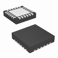
IC RX FSK 315-915MHZ 20VQFN
Manufacturer
Silicon Laboratories Inc
Series
EZRadio®r
Type
ISM Receiverr
Specifications of SI4313-B1-FM
Package / Case
20-VQFN
Mfg Application Notes
Si4313 Register Desc AppNote
Frequency
315MHz, 434MHz, 868MHz, 915MHz
Sensitivity
-118dBm
Data Rate - Maximum
128kbps
Modulation Or Protocol
FSK, GFSK, OOK
Applications
Data Logging, Health Monitors, Remote Control, Weather Station
Data Interface
PCB, Surface Mount
Antenna Connector
PCB, Surface Mount
Voltage - Supply
1.8 V ~ 3.6 V
Operating Temperature
-40°C ~ 85°C
Operating Frequency
315 MHz to 915 MHz
Operating Supply Voltage
1.8 V to 3.6 V
Maximum Operating Temperature
+ 85 C
Minimum Operating Temperature
- 40 C
Mounting Style
SMD/SMT
Supply Current
100 nA
Lead Free Status / RoHS Status
Lead free / RoHS Compliant
Features
-
Memory Size
-
Current - Receiving
-
Lead Free Status / Rohs Status
Lead free / RoHS Compliant
Other names
336-1980-5
Available stocks
Company
Part Number
Manufacturer
Quantity
Price

Company:
Part Number:
SI4313-B1-FMR
Manufacturer:
TI
Quantity:
10 000
Part Number:
SI4313-B1-FMR
Manufacturer:
SILICON LABS/芯科
Quantity:
20 000


complement of the positive offset number. The offset can be calculated with the following formula:
The adjustment range is ±160 kHz in high band and ±80 kHz in low band. For example, to compute an offset of
+50 kHz in high band mode, fo[9:0] should be set to 0A0h. For an offset of –50 kHz in high band mode, the fo[9:0]
register should be set to 360h.
3.5.3. Auto Frequency Control (AFC)
All AFC settings can be easily obtained from the excel settings calculator or by using the WDS Chip Configurator.
This is the recommended method to program all AFC settings. This section is intended to describe the operation of
the AFC in more detail to help understand the trade-offs of using AFC.The receiver supports automatic frequency
control (AFC) to compensate for frequency differences between the transmitter and receiver reference frequencies.
These differences can be caused by the absolute accuracy and temperature dependencies of the reference
crystals. Due to frequency offset compensation in the modem, the receiver is tolerant to frequency offsets up to
±0.25 times the IF bandwidth when the AFC is disabled. When the AFC is enabled, the received signal will be
centered in the pass-band of the IF filter, providing optimal sensitivity and selectivity over a wider range of
frequency offsets up to ±0.35 times the IF bandwidth. The trade-off of receiver sensitivity (at 1% PER) versus
carrier offset and the impact of AFC are illustrated in Figure 8.
When AFC is enabled, the preamble length needs to be long enough to settle the AFC. In general, one byte of
preamble is sufficient to settle the AFC. Disabling the AFC allows the preamble to be shortened from 40 bits to 32
bits. Note that with the AFC disabled, the preamble length must still be long enough to settle the receiver and to
detect the preamble (see "6.2. Preamble Length" on page 30). The AFC corrects the detected frequency offset by
changing the frequency of the Fractional-N PLL. When the preamble is detected, the AFC will freeze for the
remainder of the packet. The AFC loop includes a bandwidth limiting mechanism improving the rejection of out of
band signals. When the AFC loop is enabled, its pull-in-range is determined by the bandwidth limiter value
Add
73
74
R/W
R/W
R/W
Func/Description
Frequency Offset
Frequency Offset
Figure 8. Sensitivity at 1% PER vs. Carrier Frequency Offset
Desired Offset
fo 9:0
Rsvd
fo[7]
D7
=
--------------------------------------------------------------- -
156.25 Hz
Rsvd
=
Desired Offset
fo[6]
D6
156.25 Hz
Rev. 1.0
hbsel
Rsvd
fo[5]
D5
+
hbsel
1
Rsvd
fo[4]
D4
+
1
Rsvd
fo[3]
D3
fo 9:0
Rsvd
fo[2]
D2
fo[1]
fo[9]
D1
Si4313-B1
fo[0]
fo[8]
D0
POR Def
00h
00h
23
Related parts for SI4313-B1-FM
Image
Part Number
Description
Manufacturer
Datasheet
Request
R

Part Number:
Description:
Manufacturer:
Silicon Laboratories Inc
Datasheet:
Part Number:
Description:
SMD/C�/SINGLE-ENDED OUTPUT SILICON OSCILLATOR
Manufacturer:
Silicon Laboratories Inc
Part Number:
Description:
Manufacturer:
Silicon Laboratories Inc
Datasheet:
Part Number:
Description:
N/A N/A/SI4010 AES KEYFOB DEMO WITH LCD RX
Manufacturer:
Silicon Laboratories Inc
Datasheet:
Part Number:
Description:
N/A N/A/SI4010 SIMPLIFIED KEY FOB DEMO WITH LED RX
Manufacturer:
Silicon Laboratories Inc
Datasheet:
Part Number:
Description:
N/A/-40 TO 85 OC/EZLINK MODULE; F930/4432 HIGH BAND (REV E/B1)
Manufacturer:
Silicon Laboratories Inc
Part Number:
Description:
EZLink Module; F930/4432 Low Band (rev e/B1)
Manufacturer:
Silicon Laboratories Inc
Part Number:
Description:
I�/4460 10 DBM RADIO TEST CARD 434 MHZ
Manufacturer:
Silicon Laboratories Inc
Part Number:
Description:
I�/4461 14 DBM RADIO TEST CARD 868 MHZ
Manufacturer:
Silicon Laboratories Inc
Part Number:
Description:
I�/4463 20 DBM RFSWITCH RADIO TEST CARD 460 MHZ
Manufacturer:
Silicon Laboratories Inc
Part Number:
Description:
I�/4463 20 DBM RADIO TEST CARD 868 MHZ
Manufacturer:
Silicon Laboratories Inc
Part Number:
Description:
I�/4463 27 DBM RADIO TEST CARD 868 MHZ
Manufacturer:
Silicon Laboratories Inc
Part Number:
Description:
I�/4463 SKYWORKS 30 DBM RADIO TEST CARD 915 MHZ
Manufacturer:
Silicon Laboratories Inc
Part Number:
Description:
N/A N/A/-40 TO 85 OC/4463 RFMD 30 DBM RADIO TEST CARD 915 MHZ
Manufacturer:
Silicon Laboratories Inc