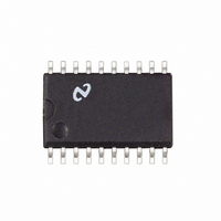
LM1865M National Semiconductor, LM1865M Datasheet - Page 8

LM1865M
Manufacturer Part Number
LM1865M
Description
IC ADVANCED FM IF SYSTEM SO20
Manufacturer
National Semiconductor
Datasheet
1.LM1865N.pdf
(16 pages)
Specifications of LM1865M
Function
FM IF System
Rf Type
FM
Package / Case
20-SOIC (0.300", 7.50mm Width)
Lead Free Status / RoHS Status
Contains lead / RoHS non-compliant
Other names
*LM1865M
Available stocks
Company
Part Number
Manufacturer
Quantity
Price
Company:
Part Number:
LM1865M
Manufacturer:
NSC
Quantity:
5 510
Part Number:
LM1865M
Manufacturer:
NS/国半
Quantity:
20 000
Application Notes
STOP TIME
An electronically tuned radio (ETR) pauses at fixed intervals
across the FM band and awaits the stop indication from the
LM1865 If within a predetermined period of time no stop
indication is forthcoming the controller circuit concludes
that there is no valid station at that frequency and will tune
to the next interval There are several time constants that
can affect the amount of time it takes the LM1865 to output
a valid stop indication on pin 16 In this section each time
constant will be discussed
Deviation Stop Time Constant
An offset voltage is generated by the AFT if the LM1865 is
tuned to either side of a station Since deviation stop detec-
tion in the LM1865 is detected by the voltage at pin 14 it is
important that this voltage move fast enough to make the
deviation stop decision within the time allowed by the con-
troller The speed at which the voltage at pin 14 moves is
governed by the RC time constant R5 C9 This time con-
stant must be chosen long enough to remove recovered
audio from pin 14 and short enough to allow for reasonable
stop detection time
Signal Level Stop Using Ultrasonic Noise Detection
As previously mentioned the R6 C8 time constant on pin 12
is necessary to filter the noise spikes on the output of the
internal comparator in the LM1865 This time constant also
determines the level stop time When the voltage at pin 12
is above a threshold voltage of about 0 6V the stop output
is low The maximum voltage at pin 12 is about 0 8V The
level stop time is dominated by the amount of time it takes
the voltage at pin 12 to fall from 0 8V to 0 6V The voltage at
pin 12 follows an exponential decay with RC time constant
given by R6 C8 For example if R6
the stop time is given by
which yields t
threshold at pin 12 has a high temperature dependence and
can move as much as 100 mV in either direction
t
e b
(24k) (2 2 F)
e
15 ms It should be noted that the 0 6V
n
0 6
0 8
(Continued)
e
25k and C8
e
2 2 F
8
Signal Level Stop Using the Meter Output Pin 8
As mentioned previously R6 C8 is not necessary when the
meter output is used to drive pin 13 Consequently this time
constant is not a factor in determining the stop time Howev-
er the speed at which the meter voltage can move may
become important in this regard This speed is a function of
the resistive load on pin 8 and filter capacitance C5
AGC Time Constant
In tuning from a strong station to a weaker station above the
level stop threshold the AGC voltage will move in order to
try to maintain a constant tuner output The AGC voltage
must move sufficiently fast so that the tuner is gain in-
creased to the point that the level stop indicates a valid
station This time constant is controlled by R11 and C13
DISTORTION COMPENSATION CIRCUIT
The quadrature detector of the LM1865 has been designed
with a special circuit that compensates for distortion gener-
ated by the non-linear phase characteristic of the quadra-
ture coil This circuit not only has the effect of reducing dis-
tortion but also desensitizes the distortion as a function of
tuning characteristic As a result low distortion is achieved
with a single tuned quad coil without the need for a double
tuned coil which is costly and difficult to adjust on a produc-
tion basis The lower distortion has been achieved without
any degradation of the noise floor of the audio output Futh-
ermore the compensation circuit first-order cancels the ef-
fect of quadrature coil Q on distortion
When measuring the total harmonic distortion (THD) of the
LM1865 it is imperative that a low distortion RF generator
be used In the past it has been possible to cancel out dis-
tortion in the generator by adjustment of the quadrature coil
This is because centering the quadrature coil at other than
the point of inflection on the S-curve introduces 2nd har-
monic distortion which can cancel 2nd harmonic distortion
in the generator Thus low THD numbers may have been
obtained wrongly Large AFT offsets asymmetrical off tuning
characteristic and less than minimum THD will be observed
if alignment of the quadrature coil is done with a high distor-
tion RF generator
Care must also be taken in choosing ceramic filters for the
LM1865 It is important to use filters with good group delay
characteristics and wide enough bandwidth to pass enough
FM sidebands to achieve low distortion


