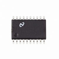
LM1865M National Semiconductor, LM1865M Datasheet - Page 13

LM1865M
Manufacturer Part Number
LM1865M
Description
IC ADVANCED FM IF SYSTEM SO20
Manufacturer
National Semiconductor
Datasheet
1.LM1865N.pdf
(16 pages)
Specifications of LM1865M
Function
FM IF System
Rf Type
FM
Package / Case
20-SOIC (0.300", 7.50mm Width)
Lead Free Status / RoHS Status
Contains lead / RoHS non-compliant
Other names
*LM1865M
Available stocks
Company
Part Number
Manufacturer
Quantity
Price
Company:
Part Number:
LM1865M
Manufacturer:
NSC
Quantity:
5 510
Part Number:
LM1865M
Manufacturer:
NS/国半
Quantity:
20 000
Application Notes
In order to make the calculation in equation (4) the con-
stants a A1 A2 must first be determined This is done by
the following procedure
1 Connect together two RF generators and apply them to
2 Connect a spectrum analyzer to the tuner output Most
3 Disconnect the AGC line to the tuner Make sure that the
4 Adjust the two RF generators for about 1 mV input and to
5 Note the three output levels in volts
6 Knowing the tuner input levels for V
7 A1 and A2 are calculated according to the following for-
FIGURE 13 Spectrum Analyzer Display of Tuner Output
the tuner input Since the generators will terminate each
other remove the 50
spectrum analyzers have 50
make sure that this impedance does not load the tuner
output use a FET probe connected to the spectrum ana-
lyzer The tuner output should be terminated with a ce-
ramic filter
tuner is not gain-reduced
frequencies 400 kHz and 800 kHz away from center fre-
quency ( Figure 13 )
the resulting IM
the formula
where all levels are in volts rms A typical value for ‘‘a’’
might be 2
mulas
a
A1
A2
e
e
e
V
UD1 2
V
V
IN
IN
c
IM
10
f
f
3
V
o
o
3
UD2
6
a
a
V1
V2
just measured ‘‘a’’ is calculated from
400 kHz
800 kHz
termination at the tuner input
(Continued)
input impedances To
UD1
and V
TL H 7509– 15
UD2
and
(5)
(6)
(7)
13
If the wide band threshold was set to V
single in-band station reached the level V
output AGC action would start to take place For this rea-
son it is hoped that V
for maximum signal-to-noise If however this is not the
case consideration might be given to improving the inter-
modulation performance of the tuner
The lower limit for V
achieves the best possible signal-to-noise ratio in the recov-
ered audio In general it is desirable to set V
the upper limit rather than the lower limit This is done to
prevent AGC action within the narrow band loop except
when there is a possibility of an IM
The wide band threshold at the pin 20 input to the LM1865
is fixed at 12 mVrms Generally speaking if pin 20 were
driven directly from the tuner output V
Therefore in general pin 20 is not connected directly to the
tuner output Instead the tuner output is attenuated and then
applied to pin 20 Increasing attenuation increases the wide
band threshold V
Pin 20 has an input impedance at 10 7 MHz that can be
modeled as a 500
giving a total impedance of 940
to attenuate the input to pin 20 is with the arrangement
shown in Figure 14
Notice that pin 20 must be AC coupled to the tuner output
and that C1 is a bypass capacitor R1 adjusts the amount of
attenuation to pin 20 The wide band threshold will roughly
increase by a factor of (R1
AGC CIRCUIT USED AS A CONVENTIONAL AGC
If for some reason the dual AGC thresholds are not desired
it is easy to use the LM1865 as a more conventional
LM3189 type of AGC This is accomplished by AC coupling
the pin 20 input after the ceramic filters rather than before
the filters Thus as with the LM3189 only in-band signals
will be able to activate the AGC
FIGURE 14 Wide Band Threshold Adjustment
WB
resistor in series with a 19 pF capacitor
WBUL
WB
is the minimum tuner output that
is above the level that will allow
a
940 ) 940
K
b
3
greater than V
58 Thus an easy way
WB
WBUL
WBUL
would be too low
WB
then when a
at the tuner
TL H 7509 – 16
closer to
NB


