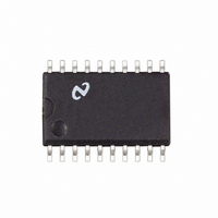
LM1865M National Semiconductor, LM1865M Datasheet - Page 10

LM1865M
Manufacturer Part Number
LM1865M
Description
IC ADVANCED FM IF SYSTEM SO20
Manufacturer
National Semiconductor
Datasheet
1.LM1865N.pdf
(16 pages)
Specifications of LM1865M
Function
FM IF System
Rf Type
FM
Package / Case
20-SOIC (0.300", 7.50mm Width)
Lead Free Status / RoHS Status
Contains lead / RoHS non-compliant
Other names
*LM1865M
Available stocks
Company
Part Number
Manufacturer
Quantity
Price
Company:
Part Number:
LM1865M
Manufacturer:
NSC
Quantity:
5 510
Part Number:
LM1865M
Manufacturer:
NS/国半
Quantity:
20 000
Application Notes
First examine what happens with a single in-band signal as
we vary the strength of this signal Figures 6 and 7 illustrate
what happens at the tuner and AGC outputs
Prime indicates referenced to tuner input
FIGURE 6
FIGURE 7
(Continued)
TL H 7509–10
FIGURE 9
10
ure 6 relatively constant
Figures 8 and 9 illustrate what happens at the tuner and
In Figure 7 there is no AGC output until the tuner output
equals the wide band threshold At this point both SW2 and
SW1 are closed and the AGC holds the tuner output in Fig-
Another simple case to examine is that of the single out-of-
band signal Here there is no AGC output even if the signal
exceeds V
ters prevent the out-of-band signal from getting to the input
of the IF With no signal at the IF input there is no meter
output and SW1 is open which means No AGC
AGC outputs when the strength of an in-band signal is var-
ied in the presence of a strong out-of-band signal (i e
greater than V
For this example the in-band signal at the tuner output will
be referred to as V
signal as V
In Figure 9 we see that there is no AGC output until the
tuner output exceeds the narrow band threshold V
this point V
desired signal at the tuner input results in an AGC current
that tries to hold the desired signal at the tuner output con-
stant This gain reduction of the tuner forces the undesired
signal at the tuner output to fall At the point that V
es the wide band threshold no further gain reduction can
occur as V
point control of the AGC shifts from the meter output
(narrow band loop) to the out-of-band signal (wide band
loop) Here V
FIGURE 8
o
WB
UD
m l
would fall below V
WB
(undesired signal)
UD
There is no output because the ceramic fil-
1V and SW1 closes Further increase of the
) which is held constant at the tuner input
is held constant along with the AGC
D
(desired signal) and the out-of-band
WB
(refer to Figure 5 ) At this
TL H 7509 – 11
UD
NB
reach-
At


