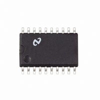
LM1865M National Semiconductor, LM1865M Datasheet - Page 2

LM1865M
Manufacturer Part Number
LM1865M
Description
IC ADVANCED FM IF SYSTEM SO20
Manufacturer
National Semiconductor
Datasheet
1.LM1865N.pdf
(16 pages)
Specifications of LM1865M
Function
FM IF System
Rf Type
FM
Package / Case
20-SOIC (0.300", 7.50mm Width)
Lead Free Status / RoHS Status
Contains lead / RoHS non-compliant
Other names
*LM1865M
Available stocks
Company
Part Number
Manufacturer
Quantity
Price
Company:
Part Number:
LM1865M
Manufacturer:
NSC
Quantity:
5 510
Part Number:
LM1865M
Manufacturer:
NS/国半
Quantity:
20 000
STATIC CHARACTERISTICS
Supply Current
Pin 9 Regulator Voltage
Operating Voltage Range
Pin 18 Output Leakage Current
Pin 16 Stop Low Output Voltage
Pin 16 Stop High Output Leakage Current
Pin 15 Audio Output Resistance
Pin 1 Buffer Input Resistance
Pin 3 Buffer Output Resistance
Pin 20 Wide Band Input Resistance
Pin 8 Meter Output Resistance
DYNAMIC CHARACTERISTICS f
b
Buffer Voltage Gain
Recovered Audio
Signal-to-Noise
AM Rejection
Minimum Total Harmonic Distortion
THD at Frequency where V14
(Zero AFT Offset)
THD
AFT Offset Frequency for Low
Stop Output at Pin 16
Ultrasonic Mute Stop Level Threshold
Absolute Maximum Ratings
If Military Aerospace specified devices are required
please contact the National Semiconductor Sales
Office Distributors for availability and specifications
Supply Voltage Pin 17
Package Dissipation (Note 1)
Storage Temperature Range
Operating Temperature Range
Max Voltage on Pin 16 (Stop Output)
Electrical Characteristics
Test Circuit T
3 dB Limiting Sensitivity
g
10 kHz from Frequency where V14
A
e
Parameter
25 C V
a
e
e
V9
12V S1 in position 2 S2 in position 1 and S3 in position 2 unless indicated otherwise
MOD
e
400 Hz f
b
e
b
55 C to
20 C to
V9
o
e
a
(See Note 2)
Pin 20 Open V
S1 in Position 1 S2 in Position 3
S2 in Position 2 V14
Measured at DC
Measured at DC
Measured at DC
IF Only (See Note 3)
V
V
V
V14
V
V
V
V
V
V
Offset
V14
V
f
S2 in Position 3
Amount of Deviation where V16
MOD
a
IN
IF
IF
IF
IF
IF
IF
IF
IF
IF
150 C
10 7 MHz Deviation
2 0W
85 C
Pin 1
e
e
e
e
e
e
e
e
e
16V
16V
e
e
e
10 mVrms V14
10 mVrms V14
1 mV 30% AM Mod
10 mV 30% AM Mod
10 mV
10 mV Tune until V14
10 mV
10 mV S2 in Position 3 f
10 mV
e
V9
V9 S1 in Position 3 (See Note 5)
100 kHz
e
(Frequency for Pin 16 Low)
(Frequency where V14
2
10 mVrms at 10 7 MHz
Conditions
IF
Soldering Information
See AN-450 ‘‘Surface Mounting Methods and Their Effect
on Product Reliability’’ for other methods of soldering sur-
face mount devices
e
Dual-In-Line Package
Small Outline Package
0 S3 in Position 1
Soldering (10 seconds)
Vapor Phase (60 seconds)
Infrared (15 seconds)
e
e
e
e
V9
V9
V9 (See Note 4)
g
75 kHz
e
MOD
V9
e
V9)
e
b
Low
0
Min
275
7 3
19
70
50
50
0 15
g
Typ
350
350
320
5 7
0 1
0 3
0 1
4 7
0 1
0 1
33
22
84
60
60
60
60
2
1
50
Max
0 35
0 45
120
470
45
16
25
260 C
215 C
220 C
mVrms
Units
kHz
kHz
Vrms
mA
k
k
dB
dB
dB
dB
%
%
%
V
V
V
A
A


