DVK-WLM400 Laird Technologies, DVK-WLM400 Datasheet - Page 12
DVK-WLM400
Manufacturer Part Number
DVK-WLM400
Description
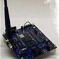
DEVELOPMENT KIT WISM+
Manufacturer
Laird Technologies
Type
Transceiverr
Datasheet
1.DVK-WLM400.pdf
(43 pages)
Specifications of DVK-WLM400
Frequency
2.4GHz
Processor Series
WISM+
Silicon Manufacturer
Laird Technologies
Kit Application Type
Communication & Networking
Application Sub Type
Wi-Fi Intelligent Serial
Kit Contents
PCB, 2x Antennas, Power Adapter, USB Cable, RS-232
Rohs Compliant
Yes
For Use With/related Products
WLM400
Lead Free Status / RoHS Status
Lead free / RoHS Compliant
Lead Free Status / RoHS Status
Lead free / RoHS Compliant, Lead free / RoHS Compliant


WISM+ DVK MANUAL
Version 1.00
Page 7
2.4 POWER/GND
2.4.1 DC Power Jack
The DC power jack accepts a 2mm plug from the AC/DC wall-brick power supply adapter. It is recommended that you
use the wall-brick power supply which is shipped with the Developer Kit, although, the input voltage range is 5 to 25
Volts (plus on the center).
2.4.2 Power Switch
The power switch when in the ON position will connect the DC power jack to the input of the switching power supply,
providing power to the entire development kit and the WISM+.
2.4.3 Switching Power Supply
The input to this switching power supply is provided from the DC power jack and is protected for reverse polarity with a
series diode. The output of the switching power supply provides power (3.3V) to the entire development board circuitry
as well as the WISM+.
2.4.4 WISM+ Input Power Jumper
This is a 4 position, dual row header. The two lower pins are connected to the WISM+ VCC input pins, and the two
upper pins are connected to the output of the 3.3V Dev Kit switching power supply. For normal operation, only one
jumper need be installed (shorting an upper pin to a lower pin).
To make WISM+ current measurements, remove the jumper and connect an ammeter between an upper and a lower
pin.
To insert an external DC power input, connect a power supply ground to one of the ground pads, and the positive side
of the power supply to one of the lower input power pins.
2.4.5 Ground Pads
These three thru-hole vias are made available simply to allow the user to have access to a system ground.
2.5 LEDs/INDICATORS
2.5.1 Power LED
This LED indicates DC power is being supplied to the WISM+ (DC power connection is made to the Dev Kit board and
the ON/OFF switch is in the ON position.
2.5.2 RUN LED
This LED is the WISM+ heartbeat. It will blink fast at boot time, pause, and then blink at a 1Hz rate once the WISM+
processor system has booted. This LED is driven by the WISM+ “HEARTBEAT” pin (WISM+ pin# 57).
2.5.3 WLAN LED
This LED will be lit when the WISM+ is wirelessly connected to another device (or joined a network). This LED is
driven by the WISM+ “
” pin (WISM+ pin#59)
CONNECTED
2.5.4 SPI
This LED will be lit whenever the SPI port is being used as the host interface, and communications are active over the
SPI port.
© Laird Technology 2010
Related parts for DVK-WLM400
Image
Part Number
Description
Manufacturer
Datasheet
Request
R

Part Number:
Description:
BLUETOOTH EVAL BOARD BTM511
Manufacturer:
Laird Technologies
Datasheet:

Part Number:
Description:
Bluetooth / 802.15.1 Modules & Development Tools BLUETTH AT Data MODLE, No ANT DEVKIT
Manufacturer:
Laird Technologies
Part Number:
Description:
Bluetooth / 802.15.1 Modules & Development Tools BLUETTH Multimed MODLE, No ANT DEVKIT
Manufacturer:
Laird Technologies
Datasheet:

Part Number:
Description:
BLUETOOTH MODULE DEVELOPMENT KIT
Manufacturer:
Laird Technologies
Part Number:
Description:
Bluetooth 2.0 AT Data Module, Internal Antenna Development Kit
Manufacturer:
Laird Technologies

Part Number:
Description:
BT MM DEV KIT
Manufacturer:
Laird Technologies
Datasheet:
Part Number:
Description:
Bluetooth / 802.15.1 Modules & Development Tools BLUETTH HCI Data MDLE INTRNLANT DVKIT
Manufacturer:
Laird Technologies
Datasheet:
Part Number:
Description:
Bluetooth / 802.15.1 Modules & Development Tools BLUETTHMultimedMODLE Plus No Ant DEVKIT
Manufacturer:
Laird Technologies
Part Number:
Description:
Bluetooth / 802.15.1 Modules & Development Tools BLUETTH HCI Data MDLE No ANT DVKIT
Manufacturer:
Laird Technologies
Datasheet:

Part Number:
Description:
KIT FOR PRM113
Manufacturer:
Laird Technologies
Datasheet:

Part Number:
Description:
DEV KIT PRM122
Manufacturer:
Laird Technologies
Datasheet:
Part Number:
Description:
DEV KIT PRM123
Manufacturer:
Laird Technologies
Datasheet:

Part Number:
Description:
KIT FOR PRM112
Manufacturer:
Laird Technologies
Datasheet:
Part Number:
Description:
DEV KIT PRM121
Manufacturer:
Laird Technologies
Datasheet:

Part Number:
Description:
Bluetooth / 802.15.1 Modules Class2 v2.1+EDR Kit AT Data, Int Ant,SSP
Manufacturer:
Laird Technologies Wireless M2M
Datasheet: