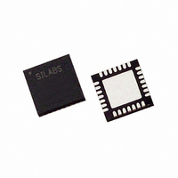
C8051F311 Silicon Laboratories Inc, C8051F311 Datasheet - Page 9

C8051F311
Manufacturer Part Number
C8051F311
Description
IC 8051 MCU 16K FLASH 28MLP
Manufacturer
Silicon Laboratories Inc
Series
C8051F31xr
Specifications of C8051F311
Core Processor
8051
Core Size
8-Bit
Speed
25MHz
Connectivity
SMBus (2-Wire/I²C), SPI, UART/USART
Peripherals
POR, PWM, Temp Sensor, WDT
Number Of I /o
25
Program Memory Size
16KB (16K x 8)
Program Memory Type
FLASH
Ram Size
1.25K x 8
Voltage - Supply (vcc/vdd)
2.7 V ~ 3.6 V
Data Converters
A/D 17x10b
Oscillator Type
Internal
Operating Temperature
-40°C ~ 85°C
Package / Case
28-VQFN Exposed Pad, 28-HVQFN, 28-SQFN, 28-DHVQFN
Lead Free Status / RoHS Status
Contains lead / RoHS non-compliant
Eeprom Size
-
Available stocks
Company
Part Number
Manufacturer
Quantity
Price
Part Number:
C8051F311-GM
Manufacturer:
SILICONLABS/芯科
Quantity:
20 000
Part Number:
C8051F311-GMR
Manufacturer:
SILICON LABS/芯科
Quantity:
20 000
17. Timers
18. Programmable Counter Array
19. Revision Specific Behavior
20. C2 Interface
Figure 16.8. SPI Master Timing (CKPHA = 0)........................................................ 183
Figure 16.9. SPI Master Timing (CKPHA = 1)........................................................ 183
Figure 16.10. SPI Slave Timing (CKPHA = 0)........................................................ 184
Figure 16.11. SPI Slave Timing (CKPHA = 1)........................................................ 184
Figure 17.1. T0 Mode 0 Block Diagram.................................................................. 188
Figure 17.2. T0 Mode 2 Block Diagram.................................................................. 189
Figure 17.3. T0 Mode 3 Block Diagram.................................................................. 190
Figure 17.4. Timer 2 16-Bit Mode Block Diagram .................................................. 195
Figure 17.5. Timer 2 8-Bit Mode Block Diagram .................................................... 196
Figure 17.6. Timer 3 16-Bit Mode Block Diagram .................................................. 199
Figure 17.7. Timer 3 8-Bit Mode Block Diagram .................................................... 200
Figure 18.1. PCA Block Diagram............................................................................ 203
Figure 18.2. PCA Counter/Timer Block Diagram.................................................... 204
Figure 18.3. PCA Interrupt Block Diagram ............................................................. 205
Figure 18.4. PCA Capture Mode Diagram.............................................................. 206
Figure 18.5. PCA Software Timer Mode Diagram .................................................. 207
Figure 18.6. PCA High Speed Output Mode Diagram............................................ 208
Figure 18.7. PCA Frequency Output Mode ............................................................ 209
Figure 18.8. PCA 8-Bit PWM Mode Diagram ......................................................... 210
Figure 18.9. PCA 16-Bit PWM Mode...................................................................... 211
Figure 18.10. PCA Module 4 with Watchdog Timer Enabled ................................. 212
Figure 19.1. Reading Package Marking ................................................................. 221
Figure 20.1. Typical C2 Pin Sharing....................................................................... 225
Rev. 1.7
C8051F310/1/2/3/4/5/6/7
9


