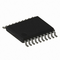
ATTINY167-15XZ Atmel, ATTINY167-15XZ Datasheet - Page 172

ATTINY167-15XZ
Manufacturer Part Number
ATTINY167-15XZ
Description
MCU AVR 16K FLASH 15MHZ 20-TSSOP
Manufacturer
Atmel
Series
AVR® ATtinyr
Datasheet
1.ATTINY167-15MD.pdf
(283 pages)
Specifications of ATTINY167-15XZ
Core Processor
AVR
Core Size
8-Bit
Speed
16MHz
Connectivity
I²C, LIN, SPI, UART/USART, USI
Peripherals
Brown-out Detect/Reset, POR, PWM, Temp Sensor, WDT
Number Of I /o
16
Program Memory Size
16KB (8K x 16)
Program Memory Type
FLASH
Eeprom Size
512 x 8
Ram Size
512 x 8
Voltage - Supply (vcc/vdd)
2.7 V ~ 5.5 V
Data Converters
A/D 11x10b
Oscillator Type
Internal
Operating Temperature
-40°C ~ 125°C
Package / Case
20-TSSOP
For Use With
ATSTK600-SOIC - STK600 SOCKET/ADAPTER FOR SOIC
Lead Free Status / RoHS Status
Lead free / RoHS Compliant
- Current page: 172 of 283
- Download datasheet (5Mb)
15.5.5.2
15.5.6
15.5.6.1
15.5.6.2
172
ATtiny87/ATtiny167
Bit Timing
Busy Signal in UART Mode
Baud rate Generator
Re-synchronization in LIN Mode
When the busy signal is set, some registers are locked, user writing is not allowed:
If the busy signal is set, the only available commands are:
Note that, if another command is entered during busy signal, the new command is not vali-
dated and the LOVRERR bit flag of the LINERR register is set. The on-going transfer is not
interrupted.
During the byte transmission, the busy signal is set. This locks some registers from being
written:
The busy signal is not generated during a byte reception.
The baud rate is defined to be the transfer rate in bits per second (bps):
Equation for calculating baud rate:
Equation for setting LINDIV value:
Note that in reception a majority vote on three samplings is made.
When waiting for Rx Header, LBT[5..0] = 32 in LINBTR register. The re-synchronization
begins when the BREAK is detected. If the BREAK size is not in the range (10.5 bits min., 28
bits max. — 13 bits nominal), the BREAK is refused. The re-synchronization is done by adjust-
ing LBT[5..0] value to the SYNCH field of the received header (0x55). Then the PROTECTED
IDENTIFIER is sampled using the new value of LBT[5..0].
• “LIN Control Register” - LINCR - except LCMD[2..0], LENA & LSWRES,
• “LIN Baud Rate Registers” - LINBRRL & LINBRRH,
• “LIN Data Length Register” - LINDLR,
• “LIN Identifier Register” - LINIDR,
• “LIN Data Register” - LINDAT.
• LCMD[1..0] = 00
• LENA = 0 and/or LCMD[2] = 0, the kill command is taken into account immediately,
• LSWRES = 1, the reset command is taken into account immediately.
• “LIN Control Register” - LINCR - except LCMD[2..0], LENA & LSWRES,
• “LIN Data Register” - LINDAT.
• BAUD: Baud rate (in bps),
•
• LDIV[11..0]: Contents of LINBRRH & LINBRRL registers - (0-4095), the pre-scaler
• LBT[5..0]: Least significant bits of - LINBTR register- (0-63) is the number of samplings in a
f
receives clk
LIN or UART bit (default value 32).
clk
i/o
: System I/O clock frequency,
i/o
as input clock.
b
, the abort command is taken into account at the end of the byte,
BAUD = fclk
LDIV[11..0] = ( fclk
i/o
/ LBT[5..0] x (LDIV[11..0] + 1)
i/o
/ LBT[5..0] x BAUD ) - 1
7728G–AVR–06/10
Related parts for ATTINY167-15XZ
Image
Part Number
Description
Manufacturer
Datasheet
Request
R

Part Number:
Description:
Manufacturer:
Atmel Corporation
Datasheet:

Part Number:
Description:
Manufacturer:
Atmel Corporation
Datasheet:

Part Number:
Description:
MCU AVR 16K FLASH 15MHZ 32-QFN
Manufacturer:
Atmel
Datasheet:

Part Number:
Description:
IC MCU AVR 16K FLASH 20TSSOP
Manufacturer:
Atmel
Datasheet:

Part Number:
Description:
MCU AVR 16K FLASH 15MHZ 32-QFN
Manufacturer:
Atmel
Datasheet:

Part Number:
Description:
MCU AVR 16K FLASH 15MHZ 20-SOIC
Manufacturer:
Atmel
Datasheet:

Part Number:
Description:
MCU AVR 16K FLASH 15MHZ 20-TSSOP
Manufacturer:
Atmel
Datasheet:

Part Number:
Description:
IC MCU AVR 16K FLASH 20SOIC
Manufacturer:
Atmel
Datasheet:


