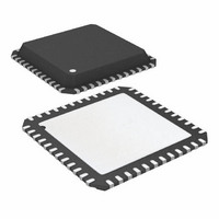
ATA6613P-PLQW Atmel, ATA6613P-PLQW Datasheet - Page 324

ATA6613P-PLQW
Manufacturer Part Number
ATA6613P-PLQW
Description
MCU W/LIN TXRX REG WTCHDG 48-QFN
Manufacturer
Atmel
Series
AVR® ATA66 LIN-SBCr
Datasheet
1.ATA6612-EK.pdf
(364 pages)
Specifications of ATA6613P-PLQW
Core Processor
AVR
Core Size
8-Bit
Speed
16MHz
Connectivity
I²C, LIN, SPI, UART/USART
Peripherals
Brown-out Detect/Reset, POR, PWM, WDT
Number Of I /o
23
Program Memory Size
16KB (16K x 8)
Program Memory Type
FLASH
Eeprom Size
512 x 8
Ram Size
1K x 8
Voltage - Supply (vcc/vdd)
2.7 V ~ 5.5 V
Data Converters
A/D 8x10b
Oscillator Type
Internal
Operating Temperature
-40°C ~ 125°C
Package / Case
48-QFN Exposed Pad
Processor Series
ATA6x
Core
AVR8
Data Bus Width
8 bit
Data Ram Size
1 KB
Interface Type
I2C, SPI, USART
Maximum Clock Frequency
16 MHz
Number Of Programmable I/os
23
Number Of Timers
3
Maximum Operating Temperature
+ 125 C
Mounting Style
SMD/SMT
Minimum Operating Temperature
- 40 C
On-chip Adc
10 bit, 8 Channel
Lead Free Status / RoHS Status
Lead free / RoHS Compliant
Available stocks
Company
Part Number
Manufacturer
Quantity
Price
Company:
Part Number:
ATA6613P-PLQW
Manufacturer:
ATMEL
Quantity:
5 000
Part Number:
ATA6613P-PLQW
Manufacturer:
ATMEL/爱特梅尔
Quantity:
20 000
- Current page: 324 of 364
- Download datasheet (7Mb)
6.26.2.1
7. 2-wire Serial Interface Characteristics
Table 7-1
2-wire Serial Interface meets or exceeds these requirements under the noted conditions.
Timing symbols refer to
Table 7-1.
324
Symbol
Notes:
Vhys
VOL
tSP
tof
VIH
VIL
tr
I
(1)
i
(1)
(1)
(1)
(1)
1. In Atmel ATA6612/ATA6613, this parameter is characterized and not 100% tested.
2. Required only for f
3. C
4. f
5. This requirement applies to all Atmel ATA6612/ATA6613 2-wire Serial Interface operation. Other devices connected to the
6. The actual low period generated by the Atmel ATA6612/ATA6613 2-wire Serial Interface is (1/f
7. The actual low period generated by the Atmel ATA6612/ATA6613 2-wire Serial Interface is (1/f
Atmel ATA6612/ATA6613
describes the requirements for devices connected to the 2-wire Serial Bus. The Atmel
Parameter
Input Low-voltage
Input High-voltage
Hysteresis of Schmitt Trigger Inputs
Output Low-voltage
Rise Time for both SDA and SCL
Output Fall Time from V
Spikes Suppressed by Input Filter
Input Current each I/O Pin
2-wire Serial Bus need only obey the general f
greater than 6MHz for the low time requirement to be strictly met at f
time requirement will not be strictly met for f
nected to the bus may communicate at full speed (400kHz) with other Atmel ATA6612/ATA6613 devices, as well as any
other device with a proper t
CK
RC Oscillator Precision for LIN Slave implementation
b
2-wire Serial Bus Requirements
= capacitance of one bus line in pF.
= CPU clock frequency
Figure 7-1 on page
For LIN slave devices, the precision of the RC oscillator before and after re-synchronization
are described in the
Table 6-130. Oscillator Tolerance Before and After Re-synchronization Algorithm
SCL
Parameter
F
F
TOL_UNSYNCH
TOL_SYNCH
> 100kHz.
IHmin
LOW
to V
acceptance margin.
ILmax
(2.7V < V
326.
Clock Tolerance
Deviation of slave node clock from the nominal clock rate before
synchronization; relevant for nodes making use of
synchronization and direct SYNCH BREAK detection.
Deviation of slave node clock relative to the master node clock
after synchronization; relevant for nodes making use of
synchronization; any slave node must stay within this tolerance
for all fields of a frame which follow the SYNCH FIELD.
Note:
Table
SCL
CC
Condition
10pF < C
0.1V
3mA sink current
SCL
6-130.
> 308kHz when f
< 5.5V, -40 C to +125 C)
rate must not differ by more than ±2%.
For communication between any two nodes their bit
CC
requirement.
< V
b
< 400pF
i
< 0.9V
CC
(3)
CK
= 8MHz. Still, Atmel ATA6612/ATA6613 devices con-
SCL
= 100kHz.
20 + 0.1C
20 + 0.1C
0.05 V
0.7 V
Min
-0.5
-10
0
0
CC
CC
b
b
(2)
(2,3)
(2,3)
SCL
SCL
- 2/f
- 2/f
®
V
ATA6612/ATA6613
0.3 V
CK
CC
CK
Max
50
300
250
0.4
), thus f
10
–
), thus the low
+ 0.5
(2)
CC
9111H–AUTO–01/11
±14.0%
±2.0%
F/F
CK
Master
must be
Units
µA
ns
ns
ns
V
V
V
V
Related parts for ATA6613P-PLQW
Image
Part Number
Description
Manufacturer
Datasheet
Request
R

Part Number:
Description:
MCU W/LIN TXRX REG WTCHDG 48-QFN
Manufacturer:
Atmel
Datasheet:

Part Number:
Description:
Ata6613
Manufacturer:
ATMEL Corporation
Datasheet:

Part Number:
Description:
BOARD DEMO LIN-MCM FOR ATA6613
Manufacturer:
Atmel
Datasheet:

Part Number:
Description:
DEV KIT FOR AVR/AVR32
Manufacturer:
Atmel
Datasheet:

Part Number:
Description:
INTERVAL AND WIPE/WASH WIPER CONTROL IC WITH DELAY
Manufacturer:
ATMEL Corporation
Datasheet:

Part Number:
Description:
Low-Voltage Voice-Switched IC for Hands-Free Operation
Manufacturer:
ATMEL Corporation
Datasheet:

Part Number:
Description:
MONOLITHIC INTEGRATED FEATUREPHONE CIRCUIT
Manufacturer:
ATMEL Corporation
Datasheet:

Part Number:
Description:
AM-FM Receiver IC U4255BM-M
Manufacturer:
ATMEL Corporation
Datasheet:

Part Number:
Description:
Monolithic Integrated Feature Phone Circuit
Manufacturer:
ATMEL Corporation
Datasheet:

Part Number:
Description:
Multistandard Video-IF and Quasi Parallel Sound Processing
Manufacturer:
ATMEL Corporation
Datasheet:

Part Number:
Description:
High-performance EE PLD
Manufacturer:
ATMEL Corporation
Datasheet:

Part Number:
Description:
8-bit Flash Microcontroller
Manufacturer:
ATMEL Corporation
Datasheet:


