58372-1 Tyco Electronics, 58372-1 Datasheet - Page 3
58372-1
Manufacturer Part Number
58372-1
Description
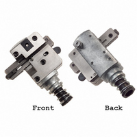
TOOL HEAD ASSEM 2MM TERMINATER
Manufacturer
Tyco Electronics
Series
MTr
Type
Crimpersr
Specifications of 58372-1
Product
Insertion Tool
Description/function
Contact crimping
Fits Cable/wire
2 mm
For Use With
2 Mm CT Connector System - MT Receptacles
Lead Free Status / RoHS Status
Not applicable / Not applicable
Lead Free Status / RoHS Status
na, Not applicable / Not applicable
Other names
58372-1
A99129
A99129


5. ADJUSTMENTS
5.1. Wire Insertion Depth
A. For Pistol Grip Manual Handle Assembly
If the wire is too deep in the contact insulation
displacement slot, remove the head from the tool and
turn the adjuster
reduce the wire insertion depth by approximately
0.20 mm [.008 in.]. Install the head onto the tool; then
terminate and inspect a sample connector.
If the wire is not deep enough in the contact insulation
displacement slot, remove the head from the tool and
turn the adjuster
will increase the wire insertion depth by approximately
0.20 mm [.008 in.]. Install the head onto the tool; then
terminate and inspect a sample connector.
B. For Pneumatic Assembly
Rev C
DANGER
4. Perform one termination cycle: the inserter will
bottom, forcing the wire between the contact slots,
and will then retract. The connector will advance to
the next contact position.
5. Release the feed pawl by pushing it forward
then move the carriage to left and remove the
connector from head assembly.
6. Inspect termination in accordance with
Application Specification 114--5103. If wire
insertion depth is incorrect or if the carriage is not
feeding properly, refer to Section 5.
Turn Counterclockwise
to Increase
Wire Insertion Depth
To avoid personal injury, ALWAYS disconnect air
supply from pneumatic power bench when
removing head from tool.
1
1
/
/
6
6
--revolution clockwise. This will
--revolution counterclockwise. This
Figure 5
(See Figure 5)
Turn Clockwise
to Reduce
Wire Insertion Depth
5.2. Carriage Feed
The carriage feed adjustment setscrew, shown in
Figure 6, controls the location of the carriage. If the
screw is positioned in too far, the feed pawl will not
engage in the carriage and the carriage will not
advance. If the screw is out too far, the carriage will
back up until the feed pawl engages, and thus, will
incorrectly position the contact to be terminated.
Adjust the carriage by turning the adjustment screw
either in or out until the contact aligns with the wire
inserter.
Once the carriage feed is adjusted correctly, the
following should be observed:
6. TERMINATION PROCEDURE
CAUTION
1. Increase the air pressure for the pneumatic
bench mount in increments of 69 kPa [10 psi] until
proper wire insertion depth is obtained.
2. If the proper wire insertion depth is not obtained,
set the air pressure to 276 kPa [40 psi], and follow
the procedure in Paragraph 5.1, A.
1. Select the applicable connector and wire to be
terminated.
2. Perform the setup procedure as described in
Section 3. Note that at the end of this procedure
the connector is in position to begin the termination
process.
Carriage Feed
Adjustment Setscrew
S
S
!
Feed
Pawl
wire inserter is aligned with the connector
contact
no movement of the connector housing occurs
as the tool is actuated
DO NOT increase the air pressure beyond
483 kPa [70 psi]; otherwise, excessive wear and
strain to the tool and head could result.
Figure 6
408- 9426
Carriage
3 of 6