58372-1 Tyco Electronics, 58372-1 Datasheet - Page 2
58372-1
Manufacturer Part Number
58372-1
Description
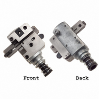
TOOL HEAD ASSEM 2MM TERMINATER
Manufacturer
Tyco Electronics
Series
MTr
Type
Crimpersr
Specifications of 58372-1
Product
Insertion Tool
Description/function
Contact crimping
Fits Cable/wire
2 mm
For Use With
2 Mm CT Connector System - MT Receptacles
Lead Free Status / RoHS Status
Not applicable / Not applicable
Lead Free Status / RoHS Status
na, Not applicable / Not applicable
Other names
58372-1
A99129
A99129


contact beam to form a reliable electrical connection
between the wire and the contact). Contact
termination is complete when the tool is actuated.
3. SETUP
The setup procedure consists of determining the size
of the connector slot, securing the connector in that
slot, and positioning the connector for termination.
Proceed as follows:
4. TEST TERMINATION AND INSPECTION
At least one termination should be performed and
inspected before starting production terminating. The
steps which follow are recommended to perform the
test termination and inspection.
Connector
Slot
2 of 6
1. To determine the size of slot required for the
connector to be terminated, push the feed pawl
forward and slide the carriage to the left as far as it
will go. Then loosen the socket head cap screw
located at bottom side of the adjustable stop
(shown in Figure 2), allowing the stop to be moved
right or left.
2. Orient the connector with the head assembly as
shown in Figure 3 — the open part of the insulation
displacement slot is up and facing the back of the
tool. Making sure that the connector slot is large
enough to accept the connector, fit the connector
in slot. Then move the adjustable stop flush
against the connector, and tighten the socket head
cap screw securing the connector to the head
assembly.
3. Push the feed pawl forward and slide the
carriage (with connector) to the right as far as it will
go. Then release the feed pawl. The connector is
now in position to begin termination.
Socket Head
Cap Screw
Adjustable
Stop
Figure 2
Push Feed
Pawl Forward
Open Part of Contact
Insulation Displacement Slot
Up and Facing Back
of Tool
1. Perform the setup procedure as described in
Section 3. Note that at the end of this procedure
the connector is in position to begin the termination
process.
2. Without inserting the wire into the wire guide,
perform one cycle. The connector will be indexed
in position for the first termination.
3. Insert an unstripped wire into the wire guide until
the wire bottoms, making sure wire is centered in
the slot. See Figure 4.
Connector
Slot
Horizontal Mount
Header
Unstripped Wire Inserted
and Bottomed in Wire Guide
Figure 3
Figure 4
Vertical Mount
Header
Adjustable Stop Moved
to Allow Connector to
Fit into Connector Slot
Back of
Tool (Ref)
Receptacle
Assembly
408- 9426
Rev C