1. INTRODUCTION
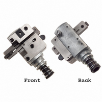
The 2 mm CT Head Assembly 58372--1 shown in
Figure 1 is designed to terminate the connectors
listed in Figure 1 onto unstripped discrete wire sizes
28 through 26 AWG with an insulation diameter of
0.85 through 1.05 mm [.033 through.041 in.].
The head is designed for use in Pistol Grip Manual
Handle Assembly 58074--1 (408--6790), Pistol Grip
Pneumatic Handle Assembly 58075--1 (408--6789), or
Pneumatic Power Bench Assembly 58338--1
(408--9393). For head installation procedures, and
setup and operation of the tools, refer to the
instruction sheets (shown in parenthesis) packaged
with the tool.
Reasons for reissue of this instruction sheet are
provided in Section 9, REVISION SUMMARY.
2. DESCRIPTION
The head assembly, when properly inserted into the
tool, serves as a guide for the connector during
termination.
E2011 Tyco Electronics Corporation, a TE Connectivity Ltd. Company
All Rights Reserved
*Trademark
TE Connectivity, TE connectivity (logo), and TE (logo) are trademarks. Other logos, product and/or Company names may be trademarks of their respective owners.
PART NUMBER
NOTE
173977--[ ]
173983--[ ]
173985--[ ]
i
2 mm CT CONNECTOR
Dimensions on this sheet are in metric units [with
U.S. customary units in brackets]. Figures and
illustrations are for reference only and are not
drawn to scale.
Receptacle Assembly
Horizontal Mount Header
Vertical Mount Header
Wire Inserter (Shown
In Up Position)
TYPE
2 mm Common Termination (CT)
Head Assembly 58372- 1
Carriage
TOOLING ASSISTANCE CENTER 1--800--722--1111
PRODUCT INFORMATION 1--800--522--6752
Connector
Slot
Figure 1
Drag
Features of the head assembly (shown in Figure 1)
and their functions are:
The wire is terminated in the connector contact using
the insulation displacement technique (a terminating
technique which inserts unstripped wire into a slotted
Wire Inserter—forces unstripped wire into the two
slotted beams of the contact.
Wire Insertion Rod and Adjuster—acts as a piston
for, and regulates travel of, the wire inserter.
Carriage—slides right and left in head assembly
and automatically advances the connector after
each termination.
Drag—prevents connector from moving out of
position after it has been advanced.
Connector Slot—opening into which connector is
secured in head assembly.
Adjustable Stop—controls the size of the connector
slot, permitting different size connectors to be
secured in head assembly.
Wire Guide—open channel into which unstripped
wire is inserted and bottomed for terminating.
Feed Pawl—when pushed forward, allows carriage
to be moved either right or left, depending on
where connector is to be located in head assembly.
Adjustable
Stop
Wire
Guide
This controlled document is subject to change.
For latest revision and Regional Customer Service,
visit our website at www.te.com
Wire Insertion
Rod and Adjuster
Feed Pawl
(Portion of Head Assembly
Shown Cut Away for Clarity)
Instruction Sheet
408- - 9426
20 APR 11
Rev C
1 of 6
LOC B