58433-1 Tyco Electronics, 58433-1 Datasheet - Page 2
58433-1
Manufacturer Part Number
58433-1
Description
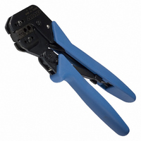
PRO CR ASSY W/RG58/59 O IS9140
Manufacturer
Tyco Electronics
Series
Pro-Crimper™ IIIr
Type
Crimpersr
Specifications of 58433-1
Tool Type
Hand Crimper
Features
Side Entry, Ratchet
Rohs Compliant
NA
Product
Crimping, Stripping & Cutting Tools & Drills
Description/function
BNC Dual O Crimp Commercial
Lead Free Status / RoHS Status
Not applicable / Not applicable
For Use With/related Products
Coaxial, RF - BNC, TNC
For Use With
8-34163-1 - CONN RING 14-16 AWG #5/16 P-G
Lead Free Status / Rohs Status
Lead free / RoHS Compliant
Other names
58433-1
A24786
A24786


3.2. Ferrule
4. INSPECTION
4.1. Visual Inspection
Inspection of the crimping dies should be made on a
regular basis to ensure that they have not become
worn or damaged. Inspect the crimp sections for
flattened, chipped, worn, or broken areas. If damage
or abnormal wear is evident, the dies must be
replaced. Refer to Section 5, PARTS
REPLACEMENT.
2
PRO-CRIMPER III Hand Crimping Tool 583433-1
Insert Center
Contact into
the Partially Closed
Crimping Dies
of 3
1. Insert the crimped center contact into the
connector body until the cable dielectric butts
against the dielectric inside the connector body.
The flared braid will then fit around the support
sleeve of the connector body.
2. Slide the ferrule forward over the braid until the
ferrule butts against the shoulder on the connector
body.
3. Place the ferrule on the approriate anvil of the
die assembly so that the shoulder on the connector
body butts against the die. See Figure 4.
4. Holding the assembly in place, close the tool
handles until the ratchet releases.
5. Remove the crimped assembly.
Ferrule
(Ref)
Figure 2
Center Contact
Slipped Over the
Center Conductor
Tyco Electronics Corporation
4.2. Measuring Die Opening
The die assembly will perform correctly as long as:
Figure 5 provides information on die opening sizes.
Crimping
Die (Ref)
a. the product specified is correct for the
application,
b. the specific die assembly is used,
c. the die assembly has been measured to
ensure that the openings are correct, and
d. the tool has been adjusted correctly.
Typical RF
Connector (Ref)
Í Í Í Í Í Í Í
Í Í Í Í Í Í Í
Í Í Í Í Í Í Í
Í Í Í Í Í Í Í
Í Í Í Í Í Í Í
Í Í Í Í Í Í Í
Í Í Í Í Í Í Í
Í Í Í Í Í Í Í
Í Í Í Í Í Í Í
Í Í Í Í Í Í Í
Í Í Í Í Í Í Í
Í Í Í Í Í Í Í
Crimping Ferrule
Flange on End of
Center that Butts
Against the Die
Figure 4
Figure 3
Shoulder On
Connector Body
Butts Against Die
Ferrule On
Anvil Of
Crimping Die
Crimping Die
Flange on the
End of the
Contact
408-9140
Rev
C