58433-1 Tyco Electronics, 58433-1 Datasheet
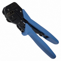
PRO CR ASSY W/RG58/59 O IS9140

58433-1

Manufacturer Part Number
58433-1
Description
PRO CR ASSY W/RG58/59 O IS9140
Manufacturer
Tyco Electronics
Series
Pro-Crimper™ IIIr
Type
Crimpersr
Datasheets

Specifications of 58433-1

Tool Type
Hand Crimper
Features
Side Entry, Ratchet
Rohs Compliant
NA
Product
Crimping, Stripping & Cutting Tools & Drills
Description/function
BNC Dual O Crimp Commercial
Lead Free Status / RoHS Status
Not applicable / Not applicable
For Use With/related Products
Coaxial, RF - BNC, TNC
For Use With
8-34163-1 - CONN RING 14-16 AWG #5/16 P-G
Lead Free Status / Rohs Status
Lead free / RoHS Compliant
Other names
58433-1
A24786
PROPER USE GUIDELINES
1. INTRODUCTION
PRO–CRIMPER III Hand Crimping Tool 58433–1
(Figure 1) is designed to crimp 50–Ohm Commercial
BNC and TNC plugs and jacks onto RG 58/U, RG
59/U, and RG 62/U cable.
Reasons for reissue of this sheet are provided in
Section 6, REVISION SUMMARY.
2. DESCRIPTION
The tool features a replaceable die assembly
(58435–1) with two ferrule crimp sections and two
center contact crimp sections. The crimp sections are
marked to identify the cable sizes used with the
connectors as follows:
E
S
S
RG 58/U crimp sections (center contact and
ferrule) are identified by the number “58”
located below the crimp section.
RG 59/U and 62/U crimp sections (center
contact and ferrule) are identified by the
number “59” located below the crimp section.
Refer to Catalog 82074
For Applicable Connectors
PRO-CRIMPER* III Hand Crimping
Tool Assembly 58433-1
Figure 1
3. CRIMPING PROCEDURE
3.1. Center Contact
1. Slide the ferrule onto the cable, then strip the
cable according to the dimensions in the
appropriate connector instruction sheet.
2. Slide the center contact onto the center
conductor of the cable; then insert the contact
assembly into the contact crimp section of the dies.
NOTE
3. Crimp the center contact by holding the contact
and cable in place; then close the tool handles until
the ratchet releases.
4. Remove the crimped center contact.
i
Make sure that the flange on the end of the
center contact butts against the crimping die. See
Figure 3.
www.tycoelectronics.com
408-9140
1

58433-1 Summary of contents

Page 1

... RG 59/U and 62/U crimp sections (center contact and ferrule) are identified by the number “59” located below the crimp section. E PRO-CRIMPER* III Hand Crimping Tool Assembly 58433-1 Figure 1 3. CRIMPING PROCEDURE 3.1. Center Contact 1. Slide the ferrule onto the cable, then strip the cable according to the dimensions in the appropriate connector instruction sheet ...

Page 2

... Figure 5 provides information on die opening sizes. Crimping Die (Ref) Typical RF Connector (Ref) Tyco Electronics Corporation 408-9140 Flange on End of Center that Butts Against the Die Í Í Í Í Í Í Í Í Í Í Í Í Í Í ...

Page 3

... Customer Service (38–35) Tyco Electronics P.O. Box 3608 Harrisburg, PA 17105–3608 6. REVISION SUMMARY Since the previous release of this document, The TE logo was applied. Figure 5 Tyco Electronics Corporation 408-9140 5. .10 [.208 in. + .004] 6. .10 [.240 in. + .004 ...