LD2T06P0 Red Lion Controls, LD2T06P0 Datasheet - Page 12
LD2T06P0
Manufacturer Part Number
LD2T06P0
Description
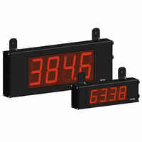
TIMER 6 DIGIT 2.25" 120VAC RED
Manufacturer
Red Lion Controls
Series
LDr
Type
Timerr
Datasheet
1.LD4T06P0.pdf
(16 pages)
Specifications of LD2T06P0
No. Of Digits / Alpha
6
Digit Height
57mm
Power Consumption
26VA
Operating Temperature Range
0°C To +50°C
Signal Input Type
Pulse
Character Size
2.25"
Ip/nema Rating
IP65 / NEMA 4X
Accuracy
±0.01% %
Connection Type
Wire Leads
Dimensions
16"L×2.25"W×4"H
Display Digit Height
2.25 "
Display Resolution
0.001 Sec. (Minimum Digit), 1 hr. (Single Digit)
Display Type
LED
Function
Timer
Material, Casing
Aluminum
Number Of Digits
6
Primary Type
Electronic
Range, Measurement
0 to 999999
Special Features
RS485/RS232 Communications
Termination
Terminal Block
Voltage, Supply
85 to 250/11 to 16 VAC/VDC
Counter Supply Voltage
85-250VAC/11-16VDC
Display Font Color
Red
Rohs Compliant
Yes
Lead Free Status / RoHS Status
Lead free / RoHS Compliant
Lead Free Status / RoHS Status
Lead free / RoHS Compliant, Lead free / RoHS Compliant
Other names
RLC119


Receiving Data From The Meter
(T), a block print request command (P) or a User Input print request. The
response from the meter is either a full field transmission or an abbreviated
transmission, depending on the selection chosen in Module 5.
Full Field Transmission
* These characters only appear in the last line of a block print.
assigned is 0, two spaces are substituted. A space follows the meter address field.
The next three characters are the register mnemonic, as shown in the Register
Identification Chart.
characters long. When a display overflow exists for a requested timer or cycle
counter value, an * (used as an overflow character) replaces a space in byte 7.
Byte 8 is always a space.
Sending Serial Commands and Data
command character must be constructed. A command string consists of a
command character, a value identifier, numerical data (if writing data to the
meter) followed by a command terminator character, * or $.
Command Chart
Command String Construction
does not respond with an error message to illegal commands. The following
procedure details construction of a command string:
1. The first 2 or 3 characters consist of the Node Address Specifier (N) followed
2. After the optional address specifier, the next character is the command
3. The next character is the register ID. This identifies the register that the
4. If constructing a value change command (writing data), the numeric data is
5. All command strings must be terminated with the string termination
Command
Data is transmitted from the meter in response to either a transmit command
The first two characters transmitted are the meter address. If the address
The numeric data is transmitted next. The numeric field (bytes 7 to 18) is 12
The remaining ten positions of this field consist of seven positions for the
When sending commands to the meter, a string containing at least one
7-18
The command string must be constructed in a specific sequence. The meter
by a 1 or 2 character node address number. The node address number of the
meter is programmable. If the node address is 0, this command and the node
address itself may be omitted. This is the only command that may be used in
conjunction with other commands.
character.
command affects. The P command does not require a register ID character. It
prints all the active selections chosen in the Print Options menu parameter.
sent next.
characters * or $. The meter does not begin processing the command string
until this character is received. See timing diagram figure for differences in
meter response time when using the * and $ terminating characters.
Byte
1, 2
4-6
19
20
21
22
23
3
N
V
R
P
T
Description
2 byte Node Address field [00-99]
<SP> (Space)
3 byte Register Mnemonic field
12 byte data field; 9 bytes for number and three bytes for decimal
points
<CR> (carriage return)
<LF> (line feed)
<SP>* (Space)
<CR>* (carriage return)
<LF>* (line feed)
Description
Node (meter)
Address Specifier
Transmit Value (read)
Value Change (write)
Reset
Block Print Request
(read)
Notes
Address a specific meter. Must be followed
by one or two digit node address. Not
required when node address = 0.
Read a register from the meter. Must be
followed by a register ID character.
Write to register of the meter. Must be
followed by a register ID character and
numeric data.
Reset a value or the output. Must be followed
by a register ID character
Initiates a block print output. Registers in the
print block are selected in Print Options.
12
requested value with decimal points positioned for the selected timer range. The
data within bytes 9 to 18 is right-aligned with leading spaces for any unfilled
positions.
last line of a block print, an extra <SP>, <CR> and <LF> are added to provide
separation between the print blocks.
Abbreviated Transmission
* These characters only appear in the last line of a block print.
leaving only the numeric part of the response.
Meter Response Examples:
1. Node address = 17, full field response, Cycle Counter = 875
2. Node address = 0, full field response, Setpoint On value = 250.5
3. Node address = 0, abbreviated response, Setpoint On value= 250, last line of
Register Identification Chart
Command String Examples:
1. Node address = 17, Write 350 to the Setpoint On value
2. Node address = 5, Read Timer value, response time of 50 msec min
3. Node address = 0, Reset Setpoint output
4. Node address = 31, Request a Block Print Output, response time of 2 msec min
Transmitting Data to the Meter
Numeric data sent to the meter must be limited to Transmit Details listed in the
Register Identification Chart. Leading zeros are ignored. The meter ignores any
decimal point and conforms the number to the appropriate display format. (For
example: The Timer range is set for tenths of a second and 25 is written to the
Timer Start register. The value of the register is now 2.5 seconds. In this case,
write a value of 250 to equal 25.0 seconds).
Note: Since the meter does not issue a reply to value change commands, follow
The end of the response string is terminated with a <CR> and <LF>. After the
The abbreviated response suppresses the node address and register mnemonic,
block print
with a transmit value command for readback verification.
ID
C
D
G
H
A
B
E
F
Byte
1-12
13
14
15
16
17
17 CNT
SPT
String: N17VF350$
String: N5TA*
String: RF*
String: N31P$
Timer
Cycle Counter
Timer Start
Timer Stop
Counter Start
Setpoint ON
(Reset Output)
Setpoint OFF
Setpoint
Time-out
Description
Description
12 byte data field, 9 bytes for number and three bytes for
decimal points
<CR> (carriage return)
<LF> (line feed)
<SP>* (Space)
<CR>* (carriage return)
<LF>* (line feed)
Value
250<CR><LF><SP><CR><LF>
250.5<CR><LF>
875 <CR><LF>
MNEMONIC
TMR
CNT
TSP
CST
SPT
SOF
STO
TST
Commands
Applicable
T, V, R
T, V, R
T, V, R
T, V
T, V
T, V
T, V
T, V
Transmit Details (T and V)
6 digit, per Timer Range
5 digit
6 digit, per Timer Range
6 digit, per Timer Range
5 digit
per Setpoint Assignment,
same as Timer or Counter
per Setpoint Assignment,
same as Timer or Counter
6 digit, mm.ss.ss format
Related parts for LD2T06P0
Image
Part Number
Description
Manufacturer
Datasheet
Request
R

Part Number:
Description:
Counter
Manufacturer:
Red Lion Controls
Datasheet:
Part Number:
Description:
Miniature Length Sensor
Manufacturer:
Red Lion Controls
Datasheet:
Part Number:
Description:
Model Lsc - Single Channel Output Length Sensor
Manufacturer:
Red Lion Controls
Datasheet: