P7S-14P Omron, P7S-14P Datasheet - Page 20
P7S-14P
Manufacturer Part Number
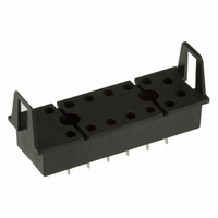
P7S-14P
Description
SOCKET PC MNT FOR G7S RELAY
Manufacturer
Omron
Series
G7Sr
Type
Socketr
Specifications of P7S-14P
Mounting Type
Through Hole
Number Of Positions
14
Termination Style
PC Pin
Current Rating
6A
Terminal Type
Through Hole
No. Of Pins
14
Svhc
No SVHC (15-Dec-2010)
Accessory Type
Socket
External Depth
47mm
External Length / Height
80.5mm
External
RoHS Compliant
Associated Relay Series
G7S
Mounting Style
Through Hole
Width
23 mm
Socket Mounting
Through Hole
Socket Terminals
Quick Connect
Rohs Compliant
Yes
Lead Free Status / RoHS Status
Lead free / RoHS Compliant
For Use With/related Products
G7S Series
For Use With
Z2362 - RELAY SAFETY 6A 24VDC PLUG-INZ2363 - RELAY SAFETY 6A 24VDC PLUG-IN
Lead Free Status / Rohs Status
Lead free / RoHS Compliant
Other names
P7S14P
Z2418
Z2418
Available stocks
Company
Part Number
Manufacturer
Quantity
Price
Company:

Part Number:
P7S-14P
Manufacturer:
Omron Electronics Inc-EMC Div
Quantity:
135


H Troubleshooting
The following table can be used for troubleshooting when Relay
operation is not normal. Refer to this table when checking the circuit
and other items. If checking the circuit reveals no abnormality, and it
appears that the fault is caused by a Relay, contact your OMRON
representative. (Do not disassemble the Relay. Doing so will make it
impossible to identify the cause of the problem.)
A Relay is composed of various mechanical parts, including a coil,
contacts, and iron core. Among these, problems occur most often
with the contacts, and next often with the coil.
(1) Operation fault
(2) Release fault
(3) Coil burning
(4) Contact welding
(5) Contact failure
(6) Abnormal contact
(7) Humming
consumption
Fault
http://www.ia.omron.com/
1. Incorrect coil rated voltage selected
2. Faulty wiring
3. Input signal not received
4. Power supply voltage drop
5. Circuit voltage drop (Be careful in particular of high-
6. Rise in operating voltage along with rise in ambient
7. Coil disconnection
1. Input signal OFF fault
2. Voltage is applied to the coil by a sneak current
3. Residual voltage by a combination circuit such as a
4. Release delay due to parallel connection of coil and
5. Contact welding
1. Unsuitable voltage applied to coil
2. Incorrect rated voltage selected
3. Short-circuit between coil layers
1. Excessive device load connected (insufficient
2. Excessive switching frequency
3. Short-circuiting of load circuit
4. Abnormal contact switching due to humming
5. Expected service life of contacts reached
1. Oxidation of contact surfaces
2. Contact abrasion and aging
3. Terminal and contact displacement due to faulty
1. Unsuitable Relay selection
2. Insufficient consideration of device load (especially
3. No contact protection circuit
4. Insufficient withstand voltage between adjacent
1. Insufficient voltage applied to coil
2. Excessive power supply ripple (DC)
3. Incorrect coil rated voltage selected
4. Slow rise in input voltage
5. Abrasion in iron core
6. Foreign material between moveable iron piece and
current devices operated nearby or wired at a
distance.)
operating temperature (especially for DC)
semiconductor circuit
capacitor
contact capacity)
handling
motor, solenoid, and lamp loads)
contacts
iron core
Probable cause
These problems, however, mostly occur as a result of external factors
such as methods and conditions of operation, and can generally be
prevented by means of careful consideration before operation and by
selecting the correct Relays.
The following table shows the main faults that may occur, their
probable causes, and suggested countermeasures to correct them.
(c)Copyright OMRON Corporation 2007 All Rights Reserved.
1. Select the correct rated voltage.
2. Check the voltage between coil terminals.
3. Check the voltage between coil terminals.
4. Check the power supply voltage.
5. Check the circuit voltage.
6. Test individual Relay operation.
7. • For coil burning, see fault (3).
1. Check the voltage between coil terminals.
2. Check the voltage between coil terminals.
3. Check the voltage between coil terminals.
4. Check the voltage between coil terminals.
5. For contact welding, see fault (4).
1. Check the voltage between coil terminals.
2. Select the correct rated voltage.
3. Recheck the operating atmosphere.
1. Check the load capacity.
2. Check the number of switches.
3. Check the load circuits.
4. For humming, see fault (7).
5. Check the contact ratings.
1. • Recheck the operating atmosphere.
2. The expected service life of the contacts has been
3. Be careful of vibration, shock, and soldering
1. Select the correct Relay.
2. Select the correct devices.
3. Add a circuit such as a spark quenching circuit.
4. Select the correct Relay.
1. Check the voltage between coil terminals.
2. Check the ripple percentage.
3. Select the correct rated voltage.
4. Make supplemental changes to circuit.
5. The expected service life has been reached.
6. Remove the foreign material.
• For disconnection due to electrical corrosion,
• Select the correct Relay.
reached.
operations.
check the polarity being applied to the coil voltage.
Countermeasures
C-15
Related parts for P7S-14P
Image
Part Number
Description
Manufacturer
Datasheet
Request
R

Part Number:
Description:
Relay Sockets & Hardware G7 RELAY TRACK MT SOCKET
Manufacturer:
Omron
Datasheet:

Part Number:
Description:
Contact OSTI
Manufacturer:
Omron
Datasheet:

Part Number:
Description:
Relay Sockets & Hardware G7 relay PCB mounting
Manufacturer:
Omron
Part Number:
Description:
Relay Sockets & Hardware SOCKET
Manufacturer:
Omron
Datasheet:

Part Number:
Description:
G6S-2GLow Signal Relay
Manufacturer:
Omron Corporation
Datasheet:
Part Number:
Description:
Compact, Low-cost, SSR Switching 5 to 20 A
Manufacturer:
Omron Corporation
Datasheet:
Part Number:
Description:
Manufacturer:
Omron Corporation
Datasheet:
Part Number:
Description:
Manufacturer:
Omron Corporation
Datasheet:
Part Number:
Description:
Manufacturer:
Omron Corporation
Datasheet:
Part Number:
Description:
Manufacturer:
Omron Corporation
Datasheet: