P7S-14P Omron, P7S-14P Datasheet - Page 2
P7S-14P
Manufacturer Part Number
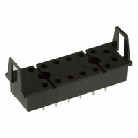
P7S-14P
Description
SOCKET PC MNT FOR G7S RELAY
Manufacturer
Omron
Series
G7Sr
Type
Socketr
Specifications of P7S-14P
Mounting Type
Through Hole
Number Of Positions
14
Termination Style
PC Pin
Current Rating
6A
Terminal Type
Through Hole
No. Of Pins
14
Svhc
No SVHC (15-Dec-2010)
Accessory Type
Socket
External Depth
47mm
External Length / Height
80.5mm
External
RoHS Compliant
Associated Relay Series
G7S
Mounting Style
Through Hole
Width
23 mm
Socket Mounting
Through Hole
Socket Terminals
Quick Connect
Rohs Compliant
Yes
Lead Free Status / RoHS Status
Lead free / RoHS Compliant
For Use With/related Products
G7S Series
For Use With
Z2362 - RELAY SAFETY 6A 24VDC PLUG-INZ2363 - RELAY SAFETY 6A 24VDC PLUG-IN
Lead Free Status / Rohs Status
Lead free / RoHS Compliant
Other names
P7S14P
Z2418
Z2418
Available stocks
Company
Part Number
Manufacturer
Quantity
Price
Company:

Part Number:
P7S-14P
Manufacturer:
Omron Electronics Inc-EMC Div
Quantity:
135


Specifications
■ Ratings
Coil
Note: 1. The rated current and coil resistance are measured at a coil temperature of 23 C with tolerances of 15%.
Contacts
■ Characteristics
Sockets
Note: 1. Use the P7S-14F-END in the ambient humidity range of 35 to 85%.
Relays with Forcibly Guided Contacts
Note: 1. The above values are initial values.
24 VDC
Rated load
Rated carry current
Maximum switching voltage
Maximum switching current
P7S-14@
Contact resistance (See note 2.)
Operating time (See note 3.)
Release time (See note 3.)
Maximum operating
frequency
Insulation resistance (See note 4.)
Dielectric strength
Vibration resistance Destruction
Shock resistance
Durability
(See note 5.)
Failure rate (P level) (reference value)
(See note 6.)
Ambient operating temperature
Ambient operating humidity
Weight
Rated voltage
2. Performance characteristics are based on a coil temperature of 23 C
3. The maximum voltage is based on an ambient operating temperature of 23 C maximum.
2. The insulation resistance was measured with a 500-VDC megohmmeter at the same locations as the dielectric strength was measured.
2. Measurement conditions: 5 VDC, 10 mA, voltage drops.
3. Measurement conditions:
4. The insulation resistance was measured with a 500-VDC
Model
Rated voltage operation
Ambient operating temperature: 23 C
Contact bounce time is not included.
megohmmeter at the same locations as the dielectric
strength was measured.
30 mA
Load
Rated current
10 A
http://www.ia.omron.com/
Mechanical
Rated load
Malfunction
Destruction
Malfunction
Mechanical
Electrical
Continuous current
800
Coil resistance
100 m
50 ms max.
50 ms max.
18,000 operations/h
1,800 operations/h
100 M
2,500 VAC, 50/60 Hz for 1 min. (1,500 VAC between contacts of same polarity)
10 to 55 Hz, 0.75-mm single amplitude (1.5-mm double amplitude)
10 to 55 Hz, 0.375-mm single amplitude (0.75-mm double amplitude)
1,000 m/s
100 m/s
10,000,000 operations min. (at approx. 18,000 operations/h)
100,000 operations min. (at the rated load and approx. 1,800 operations/h)
5 VDC, 1 mA
–25 to 70 C (with no icing or condensation)
5% to 85%
Approx. 65 g
240 VAC: 3 A, 24 VDC: 3 A
6 A
250 VAC, 24 VDC
6 A
2,000 VAC for 1 min. between terminals
2
max.
min. (at 500 VDC)
2
80% max. (V)
Must operate
Resistive load
voltage
Dielectric strength
10% min. (V)
5. The durability is for an ambient temperature of 15 to 35 C
6. The failure rate is based on an operating frequency of 60
Must release
(c)Copyright OMRON Corporation 2007 All Rights Reserved.
and an ambient humidity of 25% to 75%.
operations/min.
voltage
240 VAC: 3 A, 24 VDC: 1 A
Inductive load (cos
1,000 M min. (See note 2.)
110% (V)
Max. voltage
Insulation resistance
Approx. 0.8 W
Power consumption
= 0.4, L/R = 7 ms)
G7S
2
Related parts for P7S-14P
Image
Part Number
Description
Manufacturer
Datasheet
Request
R

Part Number:
Description:
Relay Sockets & Hardware G7 RELAY TRACK MT SOCKET
Manufacturer:
Omron
Datasheet:

Part Number:
Description:
Contact OSTI
Manufacturer:
Omron
Datasheet:

Part Number:
Description:
Relay Sockets & Hardware G7 relay PCB mounting
Manufacturer:
Omron
Part Number:
Description:
Relay Sockets & Hardware SOCKET
Manufacturer:
Omron
Datasheet:

Part Number:
Description:
G6S-2GLow Signal Relay
Manufacturer:
Omron Corporation
Datasheet:
Part Number:
Description:
Compact, Low-cost, SSR Switching 5 to 20 A
Manufacturer:
Omron Corporation
Datasheet:
Part Number:
Description:
Manufacturer:
Omron Corporation
Datasheet:
Part Number:
Description:
Manufacturer:
Omron Corporation
Datasheet:
Part Number:
Description:
Manufacturer:
Omron Corporation
Datasheet:
Part Number:
Description:
Manufacturer:
Omron Corporation
Datasheet: