P7S-14P Omron, P7S-14P Datasheet
P7S-14P
Specifications of P7S-14P
Z2418
Available stocks


Related parts for P7S-14P


P7S-14P Summary of contents
Page 1
... Accessories Sockets Type Track-mounting Common for track mounting and screw mounting Back-mounting PCB terminals http://www.ia.omron.com/ Contact configuration Rated voltage 4PST-NO, DPST-NC 24 VDC 3PST-NO, 3PST-NC Rated voltage 24 VDC --- (c)Copyright OMRON Corporation 2007 All Rights Reserved. Model G7S-4A2B G7S-3A3B Model P7S-14F-END P7S-14P-E 1 ...
Page 2
... Model Continuous current P7S-14 Note: 1. Use the P7S-14F-END in the ambient humidity range 85%. 2. The insulation resistance was measured with a 500-VDC megohmmeter at the same locations as the dielectric strength was measured. Relays with Forcibly Guided Contacts Contact resistance (See note 2.) Operating time (See note 3.) Release time (See note 3 ...
Page 3
... NC contact becomes welded, all NO contacts will maintain a minimum distance of 0.5 mm when the coil is energized. 7 Terminal Arrangement/Internal Connection Diagram (Bottom View) G7S-4A2B 22.5 max. 24 VDC 37 max. G7S-3A3B 5 min. 24 VDC (c)Copyright OMRON Corporation 2007 All Rights Reserved. G7S Mounting Hole Dimensions Fourteen, 1.8 dia. 3 ...
Page 4
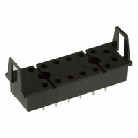
... Sockets P7S-14F-END Track-mounting Socket Indicator 40 max. 33±0.1 5 (5) P7S-14P-E Back-mounting Socket (PCB Terminals) 70.5 max. 28 ±0.2 23.5 max. Two, 6.5 dia x 8 depth 6 7 5×7=35 http://www.ia.omron.com/ Fourteen, M3.0×8 4 7.5 17 3.1 5.9 90.5 max. Terminal Arrangement/Internal Connection Diagram (Bottom View) ...
Page 5
... Safety Precautions Refer to the “Precautions for All Relays” and “Precautions for All Relays with Forcibly Guided Contacts”. ■ Precautions for Correct Use Wiring • Use one of the following wires to connect to the P7S-14F-END. Stranded wire: 0. Solid wire: 1.0 to 1.5 mm • ...
Page 6
... G7SA, G7S or G7S-@-E. Use the manufacturer’s compliance declaration to prove standard conformance. Contents of the Guidelines The Guidelines on the Application of Council Directive 73/23/EEC apply to components. Relays with PWB terminals are not covered by the Low Voltage Directive. Fig T22 14 Power source (c)Copyright OMRON Corporation 2007 All Rights Reserved. C-1 ...
Page 7
... Using DC-operated Relays, (1) Input Power Supply Ripple Using DC-operated Relays, (2) Coil Polarity Using DC-operated Relays, (3) Coil Voltage Insufficiency Lead Wire Diameters When Sockets are Used Mounting Direction When Devices Such as Microcomputers are in Proximity (c)Copyright OMRON Corporation 2007 All Rights Reserved. Page C-3 C-4 C-4 C-4 C-5 ...
Page 8
... Pattern Design for Noise Countermeasures A Noise from Coils B Noise from Contacts C High-frequency Patterns Shape of Lands Pattern Conductor Width and Thickness Conductor Pitch Securing the PCB Automatic Mounting of PCB Relays (c)Copyright OMRON Corporation 2007 All Rights Reserved. Page C-9 C-10 C-11 C-11 C-15 C-3 ...
Page 9
... B-A-2 Combining Relays and Sockets Use OMRON Relays in combination with specified OMRON Sockets. If the Relays are used with sockets from other manufacturers, it may cause problems, such as abnormal heating at the mating point due to differences in power capacity and mating properties. ...
Page 10
... The values are reference Time (t) values only. The values will depend on the operating frequency, the ambient atmosphere, and the expected level of reliability of the Relay. Be sure to check relay suitability under actual load conditions. (c)Copyright OMRON Corporation 2007 All Rights Reserved. Waveform to Steady- state ...
Page 11
... V. C Load Power supply (c)Copyright OMRON Corporation 2007 All Rights Reserved. Element selection Use the following as guides for C and R values μF per contact current ( Ω per contact voltage (V) These values depend on various factors, including the load characteristics and variations in characteristics ...
Page 12
... The resistance thermal coefficient of a copper wire is approximately 0.4% per 1°C, and the coil resistance also increases at this percentage. This catalog values for the must-operate voltage and must-release voltage are given for a coil temperature of 23°C. (c)Copyright OMRON Corporation 2007 All Rights Reserved. Incorrect ...
Page 13
... Fig. 3 C-B-10 Individual Specifications for Must-operate/ release Voltages and Operate/Release Times necessary to know the individual specifications of Correct characteristics, such as must-operate voltages, must-release voltages, operate times, and release times, please contact your OMRON representative. (c)Copyright OMRON Corporation 2007 All Rights Reserved and ...
Page 14
... The effects of corrosive gas can be reduced by the processing shown in the following table. Item Outer case, housing PCB, copper plating Connectors (c)Copyright OMRON Corporation 2007 All Rights Reserved. 2 Processing Seal structure using packing. Apply coating. Apply gold plating or rhodium plating. ...
Page 15
... Panel-mounting sockets that can be snapped 35-mm DIN Track are also available. 2. Lead Wire Screw Connections Tighten lead wire screws to a torque of 0.98 N·m (P7SA and P7S). If the screws connecting a panel-mounting socket are not sufficiently tightened, the lead wire can become detached and abnormal heating or fire can be caused by the contact failure ...
Page 16
... Noise is superimposed on the power supply line separate pattern is connected from a smoothing capacitor to supply coil power. Smoothing capacitor (c)Copyright OMRON Corporation 2007 All Rights Reserved. Minimum land diameter (mm) Tolerance 1.5 1.8 2.0 2.5 2.5 3.0 3 ...
Page 17
... Mounting method Rack mounting Screw mounting 100˚C 75˚C 50˚C 40˚C 30˚C 20˚C 10˚C 2 0.5 0 μm (c)Copyright OMRON Corporation 2007 All Rights Reserved 0.2 0.3 0.5 0.7 1 Conductor pitch (mm) Process No gap between rack's guide and PCB • Securely tighten screw. Place heavy components such as Relays on part of PCB near where screws are to be used ...
Page 18
... As shown in the above illustration, solder is available Applicability of Manual Soldering G7SA YES YES (c)Copyright OMRON Corporation 2007 All Rights Reserved. outside of the Relay terminals. If flux adheres to an area such as the bottom surface of the Relay, it will cause the insulation to deteriorate. Pressing deeply ...
Page 19
... Cooling G7SA Required G7SA 3. Do not secure the entire Relay in resin, or the Relay's characteristics will be changed. Do not exceed the maximum value for the coating's ambient operating temperature. (c)Copyright OMRON Corporation 2007 All Rights Reserved. C-14 ...
Page 20
... Refer to this table when checking the circuit and other items. If checking the circuit reveals no abnormality, and it appears that the fault is caused by a Relay, contact your OMRON representative. (Do not disassemble the Relay. Doing so will make it impossible to identify the cause of the problem.) A Relay is composed of various mechanical parts, including a coil, contacts, and iron core ...
Page 21
... When transferring devices and equipment, be sure to keep one copy of the Operating Manual and pack another copy with the device or equipment so the person receiving it will have no problem operating it. • Related International Standards: ISO 12100 Basic Concepts, General Principles for Design IEC 61508 Functional Safety of Electrical/Electronic/Programmable Electronic Safety-related Systems http://www.ia.omron.com/ WARNING (c)Copyright OMRON Corporation 2007 All Rights Reserved. ...
Page 22
... Please read and understand this catalog before purchasing the products. Please consult your OMRON representative if you have any questions or comments. WARRANTY OMRON's exclusive warranty is that the products are free from defects in materials and workmanship for a period of one year (or other period if specifi ed) from date of sale by OMRON. OMRON MAKES NO WARRANTY OR REPRESENTATION, EXPRESS OR IMPLIED, REGARDING NON-INFRINGEMENT, MERCHANTABILITY, OR FITNESS FOR PARTICULAR PURPOSE OF THE PRODUCTS ...