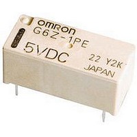
G6Z-1FE-A DC12 Omron, G6Z-1FE-A DC12 Datasheet - Page 7

G6Z-1FE-A DC12
Manufacturer Part Number
G6Z-1FE-A DC12
Description
RELAY HI FREQ 50 OHM SMD
Manufacturer
Omron
Series
G6Zr
Specifications of G6Z-1FE-A DC12
Relay Type
RF
Circuit
SPDT (1 Form C)
Contact Rating @ Voltage
0.01A @ 30VAC/DC
Coil Type
Standard
Coil Current
16.7mA
Coil Voltage
12VDC
Control On Voltage (max)
9 VDC
Control Off Voltage (min)
1.2 VDC
Mounting Type
Surface Mount
Termination Style
Gull Wing
Coil Frequency Max
2.6GHz
Coil Voltage Vdc Nom
12V
Contact Current Max
500mA
Contact Voltage Ac Nom
30V
Contact Voltage Dc Nom
30V
Coil Resistance
720ohm
Contact Configuration
SPDT
Contact Form
SPDT (1 Form C)
Contact Rating (current)
0.01A
Switching Voltage
30VAC, 30VDC - Max
Turn On Voltage (max)
9 VDC
Turn Off Voltage (min)
1.2 VDC
Features
Sealed - Fully
Contact Material
Copper (Cu), Gold (Au)
Operate Time
10ms
Release Time
10ms
Coil Power
200 mW
Operating Temperature
-40°C ~ 70°C
Lead Free Status / RoHS Status
Lead free / RoHS Compliant
Lead Free Status / RoHS Status
Lead free / RoHS Compliant, Lead free / RoHS Compliant
Other names
G6Z-1FE-ADC12
G6Z1FEADC12
G6Z1FEADC12
G6Z
Note:
124
Must Operate and Must Release
Time Distribution (See note 1.)
High-frequency Characteristics at 75 Ω
(Isolation) (See notes 1 and 2.)
High-frequency Characteristics at 50 Ω
(Isolation) (See notes 1 and 2.)
100
100
20
40
60
80
20
40
60
80
25
20
15
10
0
0
0
5
0
0
Sample: G6Z-1PE 75 Ω 5 VDC
Sample: G6Z-1PE-A 50 Ω 5 VDC
1. The tests were conducted at an ambient temperature of 23 ° C.
2. High-frequency characteristics depend on the PCB to which the Relay is mounted. Always check these characteristics, including
500
500
endurance, in the actual machine before use.
1.0
with terminating resistance
with terminating resistance
1,000
1,000
2.0
1,500
1,500
(Average value (initial value))
(Average value (initial value))
3.0
Sample: G6Z-1P
Number of Relays: 32
2,000
2,000
Frequency (MHz)
Frequency (MHz)
Must operate
Must release time
75 Ω 5 VDC
2,500 3,000
2,500 3,000
4.0
Time (ms)
N.O.
N.C.
N.O.
N.C.
5.0
Must Operate and Must Release
Bounce Time Distribution (See note 1.)
High-frequency Characteristics at 75 Ω
(Insertion Loss) (See notes 1 and 2.)
High-frequency Characteristics at 50 Ω
(Insertion Loss) (See notes 1 and 2.)
0.2
0.4
0.6
0.8
1.0
0.2
0.4
0.6
0.8
1.0
30
25
20
15
10
0
0
5
0
0
0
* Substrate loss removed
Sample: G6Z-1PE 75 Ω 5 VDC
* Substrate loss removed
Sample: G6Z-1PE-A 50 Ω 5 VDC
500
500
with terminating resistance
with terminating resistance
0.5
1,000
1,000
1,500
1,500
(Average value (initial value))
(Average value (initial value))
1.0
Must operate bounce time
Must release bounce time
Sample: G6Z-1P
Number of Relays: 32
2,000
2,000
Frequency (MHz)
Frequency (MHz)
1.5
75 Ω 5 VDC
2,500 3,000
2,500 3,000
Time (ms)
N.O
N.O.
N.C
N.C.
N.O.
N.C.
2.0
High-frequency Characteristics at 75 Ω
(Return Loss, V.SWR) (See notes 1 and 2.)
High-frequency Characteristics at 50 Ω
(Return Loss, V.SWR) (See notes 1 and 2.)
10
20
30
40
50
60
70
10
20
30
40
50
60
70
0
0
0
0
Sample: G6Z-1PE-A 50 Ω 5 VDC
Sample: G6Z-1PE 75 Ω 5 VDC
Return loss
Return loss
500
500
V.SWR
V.SWR
with terminating resistance
with terminating resistance
1,000
1,000
1,500
1,500
(Average value (initial value))
(Average value (initial value))
2,000
2,000
Frequency (MHz)
Frequency (MHz)
2,500 3,000
2,500 3,000
N.O.
N.C.
N.O.
N.C.
G6Z
1.7
1.6
1.5
1.4
1.3
1.2
1.1
1
1.7
1.6
1.5
1.4
1.3
1.2
1.1
1
W
W
V
S
R
R
V
S
.
.


