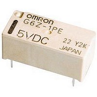
G6Z-1FE-A DC12 Omron, G6Z-1FE-A DC12 Datasheet - Page 15

G6Z-1FE-A DC12
Manufacturer Part Number
G6Z-1FE-A DC12
Description
RELAY HI FREQ 50 OHM SMD
Manufacturer
Omron
Series
G6Zr
Specifications of G6Z-1FE-A DC12
Relay Type
RF
Circuit
SPDT (1 Form C)
Contact Rating @ Voltage
0.01A @ 30VAC/DC
Coil Type
Standard
Coil Current
16.7mA
Coil Voltage
12VDC
Control On Voltage (max)
9 VDC
Control Off Voltage (min)
1.2 VDC
Mounting Type
Surface Mount
Termination Style
Gull Wing
Coil Frequency Max
2.6GHz
Coil Voltage Vdc Nom
12V
Contact Current Max
500mA
Contact Voltage Ac Nom
30V
Contact Voltage Dc Nom
30V
Coil Resistance
720ohm
Contact Configuration
SPDT
Contact Form
SPDT (1 Form C)
Contact Rating (current)
0.01A
Switching Voltage
30VAC, 30VDC - Max
Turn On Voltage (max)
9 VDC
Turn Off Voltage (min)
1.2 VDC
Features
Sealed - Fully
Contact Material
Copper (Cu), Gold (Au)
Operate Time
10ms
Release Time
10ms
Coil Power
200 mW
Operating Temperature
-40°C ~ 70°C
Lead Free Status / RoHS Status
Lead free / RoHS Compliant
Lead Free Status / RoHS Status
Lead free / RoHS Compliant, Lead free / RoHS Compliant
Other names
G6Z-1FE-ADC12
G6Z1FEADC12
G6Z1FEADC12
G6Z
Precautions
Refer to page 25 for information on general precautions. Be sure to read these precautions before using the Relay.
I
Please observe the following precautions to prevent failure to
operate, malfunction, or undesirable effect on product perfor-
mance.
High-frequency Characteristics Measurement
Method and Measurement Substrate
High-frequency characteristics for the G6Z are measured in the
way shown below. Consult your OMRON representative for
details on 50- Ω models.
Measurement Method for 75- Ω Models
Through-hole Substrate (75- Ω Models, E-shape or Y-shape)
SMD-type Substrate (75- Ω Models, E-shape or Y-shape)
132
40
40
(Unit: mm)
(Unit: mm)
Network vector analyzer
(Agilent Technologies)
Precautions for Correct Use
30
30
HP8753D
6.3
6.3
50-Ω/75-Ω adapter
(Agilent Technologies)
11852B-004
0.4
1.4
40
30
40
30
0.4
1.4
G6Z
4-dia. through-hole
0.6-dia. through-hole
4-dia. through-hole
0.6-dia. through-hole
3.59
3.91
1
1
75-Ω terminating
resistance
0.95
0.95
Substrate for High-frequency Characteristic Compensation
(75- Ω Models, E-shape or Y-shape)
Substrate Types
Material: FR-4 glass epoxy (glass cloth impregnated with epoxy
Thickness: 1.6 mm
Thickness of copper plating:18 µ m
Note:
Handling
Do not use the Relay if it has been dropped. Dropping the Relay
may adversely affect its functionality.
Protect the Relay from direct sunlight and keep the Relay under
normal temperature, humidity, and pressure.
Flow Soldering
Soldering temperature: Approx. 250 ° C (260 ° C if the DWS method
is used)
Soldering time: Approx. 5 s max. (approx. 2 s for the first time and
approx. 3 s for the second time if the DWS method is used)
Be sure to adjust the level of the molten solder so that the solder
will not overflow onto the PCB.
40
(Unit: mm)
30
0.95
1. The compensation substrate is used when measuring
2. For convenience, the diagrams of the high-frequency
3. Be sure to mount a standoff tightly to the through-hole
4. Use measuring devices, connectors, and substrates
5. Ensure that there is no pattern under the Relay. Other-
resin and copper laminated to its outer surface)
the Relay’s insertion loss. The insertion loss is ob-
tained by subtracting the measured value for the com-
pensation substrate from the measured value with the
Relay mounted to the high-frequency measurement
substrate.
measurement substrates given here apply both to
models with an E-shape terminal structure and to mod-
els with a Y-shape terminal structure.
substrate.
that are appropriate for 50 Ω and 75 Ω respectively.
wise, the impedance may be adversely affected and
the Relay may not be able to attain its full characteris-
tics.
1
30.7
20
4-dia. through-hole
0.6-dia. through-hole
G6Z


