TOOLSTICK542PP Silicon Laboratories Inc, TOOLSTICK542PP Datasheet - Page 193
TOOLSTICK542PP
Manufacturer Part Number
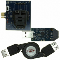
TOOLSTICK542PP
Description
PLATFORM PROG TOOLSTICK F542
Manufacturer
Silicon Laboratories Inc
Series
ToolStickr
Type
Microcontroller Programmerr
Specifications of TOOLSTICK542PP
Contents
2 Boards and USB Connecting Cable
Processor To Be Evaluated
C8051F542
Interface Type
USB
Operating Supply Voltage
2.7 V to 3.6 V
Lead Free Status / RoHS Status
Lead free / RoHS Compliant
For Use With/related Products
C8051F542
Lead Free Status / Rohs Status
Lead free / RoHS Compliant
Other names
336-1718


SFR Definition 20.1. SMB0CF: SMBus Clock/Configuration
SFR Address = 0xC1; SFR Page = 0x00
Name
Reset
Bit
1:0 SMBCS[1:0] SMBus Clock Source Selection.
Type
7
6
5
4
3
2
Bit
EXTHOLD
SMBTOE
SMBFTE
ENSMB
Name
BUSY
ENSMB
INH
R/W
7
0
SMBus Enable.
This bit enables the SMBus interface when set to 1. When enabled, the interface
constantly monitors the SDA and SCL pins.
SMBus Slave Inhibit.
When this bit is set to logic 1, the SMBus does not generate an interrupt when slave
events occur. This effectively removes the SMBus slave from the bus. Master Mode
interrupts are not affected.
SMBus Busy Indicator.
This bit is set to logic 1 by hardware when a transfer is in progress. It is cleared to
logic 0 when a STOP or free-timeout is sensed.
SMBus Setup and Hold Time Extension Enable.
This bit controls the SDA setup and hold times according to Table 20.2.
0: SDA Extended Setup and Hold Times disabled.
1: SDA Extended Setup and Hold Times enabled.
SMBus SCL Timeout Detection Enable.
This bit enables SCL low timeout detection. If set to logic 1, the SMBus forces
Timer 3 to reload while SCL is high and allows Timer 3 to count when SCL goes low.
If Timer 3 is configured to Split Mode, only the High Byte of the timer is held in reload
while SCL is high. Timer 3 should be programmed to generate interrupts at 25 ms,
and the Timer 3 interrupt service routine should reset SMBus communication.
SMBus Free Timeout Detection Enable.
When this bit is set to logic 1, the bus will be considered free if SCL and SDA remain
high for more than 10 SMBus clock source periods.
These two bits select the SMBus clock source, which is used to generate the SMBus
bit rate. The selected device should be configured according to Equation 20.1.
00: Timer 0 Overflow
01: Timer 1 Overflow
10:Timer 2 High Byte Overflow
11: Timer 2 Low Byte Overflow
R/W
INH
6
0
BUSY
R
5
0
EXTHOLD SMBTOE
R/W
Rev. 1.1
4
0
Function
R/W
3
0
SMBFTE
R/W
2
0
C8051F54x
1
0
SMBCS[1:0]
R/W
0
0
193
Related parts for TOOLSTICK542PP
Image
Part Number
Description
Manufacturer
Datasheet
Request
R

Part Number:
Description:
KIT TOOL EVAL SYS IN A USB STICK
Manufacturer:
Silicon Laboratories Inc
Datasheet:

Part Number:
Description:
TOOLSTICK DEBUG ADAPTER
Manufacturer:
Silicon Laboratories Inc
Datasheet:

Part Number:
Description:
TOOLSTICK BASE ADAPTER
Manufacturer:
Silicon Laboratories Inc
Datasheet:

Part Number:
Description:
TOOLSTICK DAUGHTER CARD
Manufacturer:
Silicon Laboratories Inc
Datasheet:

Part Number:
Description:
TOOLSTICK DAUGHTER CARD
Manufacturer:
Silicon Laboratories Inc
Datasheet:

Part Number:
Description:
TOOLSTICK DAUGHTER CARD
Manufacturer:
Silicon Laboratories Inc
Datasheet:

Part Number:
Description:
TOOLSTICK DAUGHTER CARD
Manufacturer:
Silicon Laboratories Inc
Datasheet:

Part Number:
Description:
KIT STARTER TOOLSTICK
Manufacturer:
Silicon Laboratories Inc
Datasheet:

Part Number:
Description:
KIT UNIVERSITY TOOLSTICK STARTER
Manufacturer:
Silicon Laboratories Inc
Datasheet:

Part Number:
Description:
DAUGHTER CARD TOOLSTICK F330
Manufacturer:
Silicon Laboratories Inc
Datasheet:

Part Number:
Description:
CARD DAUGHTER UNIVRSTY TOOLSTICK
Manufacturer:
Silicon Laboratories Inc
Datasheet:

Part Number:
Description:
DAUGHTER CARD TOOLSTICK F582
Manufacturer:
Silicon Laboratories Inc
Datasheet:

Part Number:
Description:
DAUGHTER CARD TOOLSTICK F500
Manufacturer:
Silicon Laboratories Inc
Datasheet:

Part Number:
Description:
DAUGHTER CARD TOOLSTICK F540
Manufacturer:
Silicon Laboratories Inc
Datasheet:

Part Number:
Description:
DAUGHTER CARD TOOLSTICK F560
Manufacturer:
Silicon Laboratories Inc
Datasheet: