TOOLSTICK542PP Silicon Laboratories Inc, TOOLSTICK542PP Datasheet - Page 131
TOOLSTICK542PP
Manufacturer Part Number
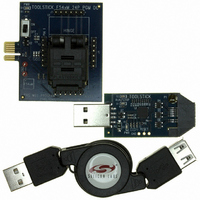
TOOLSTICK542PP
Description
PLATFORM PROG TOOLSTICK F542
Manufacturer
Silicon Laboratories Inc
Series
ToolStickr
Type
Microcontroller Programmerr
Specifications of TOOLSTICK542PP
Contents
2 Boards and USB Connecting Cable
Processor To Be Evaluated
C8051F542
Interface Type
USB
Operating Supply Voltage
2.7 V to 3.6 V
Lead Free Status / RoHS Status
Lead free / RoHS Compliant
For Use With/related Products
C8051F542
Lead Free Status / Rohs Status
Lead free / RoHS Compliant
Other names
336-1718


Important Note: If the V
is selected as a reset source. Selecting the V
lized may cause a system reset. In some applications, this reset may be undesirable. If this is not desirable
in the application, a delay should be introduced between enabling the monitor and selecting it as a reset
source. The procedure for enabling the V
state is as follows:
1. Enable the V
2. If necessary, wait for the V
3. Select the V
See Figure 16.2 for V
monitor reset. See Table 6.4 for complete electrical characteristics of the V
Note: The output of the internal voltage regulator is calibrated by the MCU immediately after any reset event. The
When programming the Flash in-system, the V
highest system reliability, the time the V
(e.g., setting the V
changing it back to the low threshold setting immediately after the Flash write operation).
Note: This delay should be omitted if software contains routines that erase or write Flash
memory.
output of the un-calibrated internal regulator could be below the high threshold setting of the VDD Monitor. If
this is the case and the V
reset (POR), the MCU will remain in reset until a POR occurs (i.e., V
POR will force the V
output of the internal regulator. The device will then exit reset and resume normal operation. It is for this reason
Silicon Labs strongly recommends that the V
value upon POR).
DD
DD
monitor as a reset source (PORSF bit in RSTSRC = 1).
DD
monitor (VDMEN bit in VDM0CN = 1).
Monitor to the high threshold setting just before the Flash write operation and then
DD
DD
DD
monitor timing; note that the power-on-reset delay is not incurred after a V
Monitor to the low threshold setting which is guaranteed to be below the un-calibrated
monitor is being turned on from a disabled state, it should be enabled before it
DD
DD
Monitor is set to the high threshold setting and if the MCU receives a non-power on
monitor to stabilize (see Table 6.4 for the V
DD
DD
Monitor is set to the high threshold setting should be minimized
monitor and configuring it as a reset source from a disabled
DD
DD
DD
Rev. 1.1
monitor as a reset source before it is enabled and stabi-
Monitor is always left in the low threshold setting (i.e., default
Monitor must be set to the high threshold setting. For the
DD
Monitor will keep the device in reset). A
DD
DD
monitor.
Monitor turn-on time).
C8051F54x
131
DD
Related parts for TOOLSTICK542PP
Image
Part Number
Description
Manufacturer
Datasheet
Request
R

Part Number:
Description:
KIT TOOL EVAL SYS IN A USB STICK
Manufacturer:
Silicon Laboratories Inc
Datasheet:

Part Number:
Description:
TOOLSTICK DEBUG ADAPTER
Manufacturer:
Silicon Laboratories Inc
Datasheet:

Part Number:
Description:
TOOLSTICK BASE ADAPTER
Manufacturer:
Silicon Laboratories Inc
Datasheet:

Part Number:
Description:
TOOLSTICK DAUGHTER CARD
Manufacturer:
Silicon Laboratories Inc
Datasheet:

Part Number:
Description:
TOOLSTICK DAUGHTER CARD
Manufacturer:
Silicon Laboratories Inc
Datasheet:

Part Number:
Description:
TOOLSTICK DAUGHTER CARD
Manufacturer:
Silicon Laboratories Inc
Datasheet:

Part Number:
Description:
TOOLSTICK DAUGHTER CARD
Manufacturer:
Silicon Laboratories Inc
Datasheet:

Part Number:
Description:
KIT STARTER TOOLSTICK
Manufacturer:
Silicon Laboratories Inc
Datasheet:

Part Number:
Description:
KIT UNIVERSITY TOOLSTICK STARTER
Manufacturer:
Silicon Laboratories Inc
Datasheet:

Part Number:
Description:
DAUGHTER CARD TOOLSTICK F330
Manufacturer:
Silicon Laboratories Inc
Datasheet:

Part Number:
Description:
CARD DAUGHTER UNIVRSTY TOOLSTICK
Manufacturer:
Silicon Laboratories Inc
Datasheet:

Part Number:
Description:
DAUGHTER CARD TOOLSTICK F582
Manufacturer:
Silicon Laboratories Inc
Datasheet:

Part Number:
Description:
DAUGHTER CARD TOOLSTICK F500
Manufacturer:
Silicon Laboratories Inc
Datasheet:

Part Number:
Description:
DAUGHTER CARD TOOLSTICK F540
Manufacturer:
Silicon Laboratories Inc
Datasheet:

Part Number:
Description:
DAUGHTER CARD TOOLSTICK F560
Manufacturer:
Silicon Laboratories Inc
Datasheet: