TOOLSTICKLINDC Silicon Laboratories Inc, TOOLSTICKLINDC Datasheet - Page 8
TOOLSTICKLINDC
Manufacturer Part Number
TOOLSTICKLINDC
Description
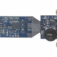
DAUGHTER CARD TOOLSTICK LIN
Manufacturer
Silicon Laboratories Inc
Series
ToolStickr
Specifications of TOOLSTICKLINDC
Module/board Type
Daughter Board
Interface Type
USB
Operating Supply Voltage
2.7 V to 3.6 V
Lead Free Status / RoHS Status
Contains lead / RoHS non-compliant
For Use With/related Products
USB Tool Stick
For Use With
336-1182 - ADAPTER USB DEBUG FOR C8051FXXX
Lead Free Status / Rohs Status
Lead free / RoHS Compliant
Other names
336-1383
Available stocks
Company
Part Number
Manufacturer
Quantity
Price
Company:

Part Number:
TOOLSTICKLINDC
Manufacturer:
Silicon Labs
Quantity:
135


ToolSt ick-LINDC
6.7. Single-Stepping Through Firmware
The IDE supports the ability to single-step through firmware one assembly instruction at a time. The IDE reads the
Flash from the device, converts the instructions to assembly and displays them in a disassembly window. The
following steps show how to open the disassembly window and single step through firmware.
1. If there is already not a breakpoint set on line of code that increments the Seconds variable, set the breakpoint
2. Start the processor using the Go button and wait till it stops on the breakpoint.
3. Select View → Debug Windows → Disassembly. The disassembly window will appear on the right-hand side
4. To execute one assembly instruction at a time, click the Step button on the toolbar or select the Debug → Step
The disassembly window has three columns. The left column is the address of the instruction in Flash. The middle
column is the instruction in hex. The right column is the disassembled instruction. The Disassembly debug window
and the capability to single-step through firmware allows a developer to see exactly what instructions are executed
and their output.
6.8. Using ToolStick Terminal
This section describes how to use ToolStick Terminal to communicate with the UART on the target microcontroller
through the ToolStick Base Adapter.
1. If the Silicon Laboratories IDE is open, close the IDE. The IDE and the ToolStick Terminal cannot communicate
2. Open ToolStick Terminal from the Start → Programs → Silicon Laboratories menu
3. Go to the ToolStick → Settings menu.
4. Under “Pin Settings”, change GPIO0 / RTS to GPIO Output - Push Pull and change the Baud Rate to 9600
5. In the top, left-hand corner of the Terminal application, available devices are shown in the drop-down
6. When ToolStick Terminal connects to the device, it resets it. The firmware starts keeping time from the reset and
In addition to the standard two UART pins (TX and RX), there are two GPIO/UART handshaking pins on the
ToolStick Base Adapter that are connected to two port pins on the target microcontroller. ToolStick Terminal is used
to configure and read/write these pins. One of these GPIO pins is connected to port pin P1.1 on the C8051F530.
The following steps describe how to change the level of one of the GPIO pins and signal the target microcontroller.
When the port pin level is low, the firmware halts the software clock.
1. In ToolStick Terminal, under Pin State Configuration, select “Set GPIO0 Logic Low” and click on “Set Selected
2. See the ToolStick Terminal reports that the clock is halted.
3. Change the GPIO0 pin state back to Logic High and notice that the firmware resumes incrementing the time.
The firmware on the C8051F530 target microcontroller does not need to be customized to use the UART and
communicate with ToolStick Terminal. The firmware on the microcontroller should write to the UART as it would in
any standard application and all of the translation is handled by the ToolStick Base Adapter.
8
using the steps described in Section 6.6.
of the IDE, if it is not already open.
menu option. The highlighted line in the disassembly window indicates the next instruction to be executed. The
blue line marker in the editor window will stay on the same C source line until all of the assembly instructions
are completed.
with the daughter card simultaneously.
and click “OK.” The rest of the default settings are correct for the C8051F530 Software Timer firmware.
Connection menu. Click Connect to connect to the device. Once connected, the Receive Data window
displays the time the firmware has been running.
outputs the time to the Terminal.
Pin States.” The firmware reads this pin in the Timer2_ISR() and stops incrementing the time if the pin is logic
low.
Rev. 0.2
Related parts for TOOLSTICKLINDC
Image
Part Number
Description
Manufacturer
Datasheet
Request
R

Part Number:
Description:
KIT TOOL EVAL SYS IN A USB STICK
Manufacturer:
Silicon Laboratories Inc
Datasheet:

Part Number:
Description:
TOOLSTICK DEBUG ADAPTER
Manufacturer:
Silicon Laboratories Inc
Datasheet:

Part Number:
Description:
TOOLSTICK BASE ADAPTER
Manufacturer:
Silicon Laboratories Inc
Datasheet:

Part Number:
Description:
TOOLSTICK DAUGHTER CARD
Manufacturer:
Silicon Laboratories Inc
Datasheet:

Part Number:
Description:
TOOLSTICK DAUGHTER CARD
Manufacturer:
Silicon Laboratories Inc
Datasheet:

Part Number:
Description:
TOOLSTICK DAUGHTER CARD
Manufacturer:
Silicon Laboratories Inc
Datasheet:

Part Number:
Description:
TOOLSTICK DAUGHTER CARD
Manufacturer:
Silicon Laboratories Inc
Datasheet:

Part Number:
Description:
KIT STARTER TOOLSTICK
Manufacturer:
Silicon Laboratories Inc
Datasheet:

Part Number:
Description:
KIT UNIVERSITY TOOLSTICK STARTER
Manufacturer:
Silicon Laboratories Inc
Datasheet:

Part Number:
Description:
DAUGHTER CARD TOOLSTICK F330
Manufacturer:
Silicon Laboratories Inc
Datasheet:

Part Number:
Description:
CARD DAUGHTER UNIVRSTY TOOLSTICK
Manufacturer:
Silicon Laboratories Inc
Datasheet:

Part Number:
Description:
DAUGHTER CARD TOOLSTICK F582
Manufacturer:
Silicon Laboratories Inc
Datasheet:

Part Number:
Description:
DAUGHTER CARD TOOLSTICK F500
Manufacturer:
Silicon Laboratories Inc
Datasheet:

Part Number:
Description:
DAUGHTER CARD TOOLSTICK F540
Manufacturer:
Silicon Laboratories Inc
Datasheet:

Part Number:
Description:
DAUGHTER CARD TOOLSTICK F560
Manufacturer:
Silicon Laboratories Inc
Datasheet: