DK-SI-2SGX90N Altera, DK-SI-2SGX90N Datasheet - Page 36
DK-SI-2SGX90N
Manufacturer Part Number
DK-SI-2SGX90N
Description
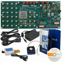
SI KIT W/SII GX EP2SGX90N
Manufacturer
Altera
Series
Stratix® IIr
Type
DSPr
Datasheet
1.DK-SI-2SGX90N.pdf
(38 pages)
Specifications of DK-SI-2SGX90N
Contents
Dev Board, Quartus®II Web Edition, Cables, Accessories, Reference Designs and Demos
For Use With/related Products
Stratix ll GX 2SGX90N
Lead Free Status / RoHS Status
Lead free / RoHS Compliant
Other names
544-1724
Available stocks
Company
Part Number
Manufacturer
Quantity
Price


Design Walkthrough With Troubleshooting and Debugging Solutions
A–8
Transceiver Signal Integrity Development Kit, Stratix II GX Edition
Troubleshooting Solutions
This section provides troubleshooting solutions. If your transaction is not
successful, review the following troubleshooting suggestions:
■
■
■
1
■
Debugging Using the SignalTap
In the kit’s Examples\SII_GX_SI_NonGUI_Design directory there is a
Quartus
design1.stp file is part of the .qar file and contains a variety of debugging
signals. The available signals are:
■
■
■
■
■
If the LED D1 is not illuminated, the system may not be receiving the
clock cycles. Ensure that the slide switch (S9) is in the oscillator
position (OSC). Also, ensure that switch 6 of the clock setting DIP
switch bank (S8) is set to OPEN.
If the LED D2 is not illuminated, the receiver cannot sync to the
transmitted data. To remedy this problem:
●
●
●
If the LED D3 is not ON, the data checker did not receive the
expected data. To remedy this problem:
●
If the display shows EE, the DIP switch selection for PMA_controls
is not correct.
All resets going into the transceivers
Status signals from transceivers: rx_freqlocked,
rx_syncstatus
Input push button and DIP switch values
Reconfiguration block signals
●
●
Data generator and checker signals
●
®
Ensure that serial loopback is ON if external loopback is not
completed.
If external loopback is completed, check the quality of the cables
used.
Assert the system_reset push button switch.
Ensure that the data pattern of the DIP switch is set to PRBS7 or
PRBS23.
High frequency data patterns do not have a data checker.
Therefore, the LED D3 will be off when high frequency patterns
are used.
Inputs and outputs of VOD, preemphasis, equalization and DC
gain values
Read, write, busy, and data valid signals
Parallel data output to the transceiver
Getting Started User Guide
II archive (.qar) file containing the example design project. The
®
II Embedded Logic Analyzer
Altera Corporation
June 2006
Related parts for DK-SI-2SGX90N
Image
Part Number
Description
Manufacturer
Datasheet
Request
R

Part Number:
Description:
KIT DEV STRATIX IV 4SGX230N/C2
Manufacturer:
Altera
Datasheet:

Part Number:
Description:
KIT DEV STRATIX IV TRANSCEIVER
Manufacturer:
Altera
Datasheet:

Part Number:
Description:
KIT DEV STRATIX V FPGA 5SGXEA7
Manufacturer:
Altera
Datasheet:

Part Number:
Description:
Programmable Logic IC Development Tools FPGA Starter Kit For Stratix V 5SGXEA7
Manufacturer:
Altera Corporation
Part Number:
Description:
Programmable Logic IC Development Tools FPGA Starter Kit For Stratix V 5SGTMC7
Manufacturer:
Altera Corporation
Part Number:
Description:
Programmable Logic IC Development Tools FPGA Starter Kit For Stratix V 5SGTMC7 ES
Manufacturer:
Altera Corporation

Part Number:
Description:
CYCLONE II STARTER KIT EP2C20N
Manufacturer:
Altera
Datasheet:
Part Number:
Description:
CPLD, EP610 Family, ECMOS Process, 300 Gates, 16 Macro Cells, 16 Reg., 16 User I/Os, 5V Supply, 35 Speed Grade, 24DIP
Manufacturer:
Altera Corporation
Datasheet:
Part Number:
Description:
CPLD, EP610 Family, ECMOS Process, 300 Gates, 16 Macro Cells, 16 Reg., 16 User I/Os, 5V Supply, 15 Speed Grade, 24DIP
Manufacturer:
Altera Corporation
Datasheet:
Part Number:
Description:
Manufacturer:
Altera Corporation
Datasheet:
Part Number:
Description:
CPLD, EP610 Family, ECMOS Process, 300 Gates, 16 Macro Cells, 16 Reg., 16 User I/Os, 5V Supply, 30 Speed Grade, 24DIP
Manufacturer:
Altera Corporation
Datasheet:
Part Number:
Description:
High-performance, low-power erasable programmable logic devices with 8 macrocells, 10ns
Manufacturer:
Altera Corporation
Datasheet:
Part Number:
Description:
High-performance, low-power erasable programmable logic devices with 8 macrocells, 7ns
Manufacturer:
Altera Corporation
Datasheet: