IRMD22381Q International Rectifier, IRMD22381Q Datasheet - Page 21
IRMD22381Q
Manufacturer Part Number
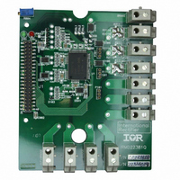
IRMD22381Q
Description
BOARD DEMO IR22381Q MOTOR DRIVER
Manufacturer
International Rectifier
Specifications of IRMD22381Q
Main Purpose
Power Management, Motor Control
Embedded
No
Utilized Ic / Part
IR22381Q / IR22381Q
Primary Attributes
3-Ph, ACIM / BLAC, 380 V @ 25 A, With Brake, 1200V DC Bus Capable
Secondary Attributes
ECONO2-PIM IGBT Module Compatible
Silicon Manufacturer
International Rectifier
Silicon Core Number
IRQ22381Q
Kit Application Type
Power Management - Motor Control
Application Sub Type
Motor Driver
Kit Contents
Board
Rohs Compliant
NA
Lead Free Status / RoHS Status
Contains lead / RoHS non-compliant


The external sensing diode should have BV>600V
(or 1200V depending on application) and low stray
capacitance (in order to minimize noise coupling and
switching delays). The diode is biased by a
dedicated circuit for IGBT driver outputs (see the
active-bias section) and by a pull-up resistor for
Brake output. When V
DSH/L pin increases too. Being internally biased to
the local supply, DSH/L or DSB voltage is
automatically clamped. When DSH/L or DSB exceed
the V
Figure 19). Comparator output is filtered in order to
avoid false desaturation detection by externally
induced noise; pulses shorter than t
out. To avoid detecting a false desaturation during
IGBT turn on, the desaturation circuit is disabled by a
Blanking signal (T
19). Blanking time is the estimated maximum IGBT
turn on time and must be not exceeded by proper
gate resistance sizing. When the IGBT is not
completely saturated after T
detected and the driver will turn off.
1.4.4
Output bridge
Desaturation event implies a large amount of current.
For that reason, IR22381 turn off strategy is based
on soft shutdown.
Eligible desaturation signals coming from DSH/L
inputs initiate the Soft Shutdown sequence (SSD).
While in SSD, the SSD pull-down is activated (R
for t
HON/LON.
Figure 20 shows the fault management circuit. In this
diagram Desat_H1,2,3 and Desat_L1,2,3 are the
internal signals triggered by the desaturation event.
IR22381 accomplishes output bridge turn off in the
following way:
In any case, after the soft shutdown period (t
IGBTs are hardly shut down (brake IGBT included).
Desaturation event generates a FAULT signal (see
Figure 11) that is latched until fault clear condition is
verified.
ss
-
-
DESAT+
– see Figure 19) to turn off the IGBT through
if the desaturated IGBT is a low side, all the
low side IGBTs are softly turned off (SSD),
while the high side IGBTs are kept in the
state they were just before the desaturation
event.
If the desaturated IGBT is a high side, it is
soflty turned off simultaneously with all the
low side IGBTs. While the remaining HS
IGBTs are kept in the state they were just
before the desaturation event.
SSD and Fault management
threshold the comparator triggers (see
BL
, see Blanking block in Figure
CE
increases, the voltage at
BL
, desaturation is
DS
are filtered
SS
ON,SS
), all
21
It must be noted that while in Soft Shut Down, both
Under Voltage fault and external Shut Down (SD)
are masked until the end of SSD. Desaturation
protection is working independently by the other
control pins and it is disabled only when the output
status is off.
Brake IGBT
Brake desaturation causes a hard shutdown for all
the IGBTs.
Fault condition is asserted and hold until cleared by
controller.
1.4.5
Fault is cleared by forcing low simultaneously LIN1,
LIN2 and LIN3 for at least t
When LIN inputs are simultaneously low and a
desaturation event happens, FAULT is activated for
a minimum amount of time of t
For the purpose of sensing the power transistor
desaturation the collector voltage is read by an
external HV diode. The diode is normally biased by
an internal pull up resistor connected to the local
supply line (V
the diode is conducting and the amount of current
flowing in the circuit is determined by the internal pull
up resistor value.
In the high side circuit, the desaturation biasing
current may become relevant for dimensioning the
bootstrap capacitor (see Figure 23). In fact, too low
pull up resistor value may result in high current
discharging significantly the bootstrap capacitor. For
that reason typical pull up resistor are in the range of
100 kΩ. This is the value of the internal pull up.
While the impedance of DSH/DSL pins is very low
when the transistor is on (low impedance path
through the external diode down to the power
transistor), the impedance is only controlled by the
pull up resistor when the transistor is off. In that case
relevant dV/dt applied by the power transistor during
the commutation at the output results in a
considerable current injected through the stray
capacitance of the diode into the desaturation
detection pin (DSH/L). This coupled noise may be
easily reduced using an active bias for the sensing
diode.
An Active Bias structure is available DSH/L pin. The
DSH/L pins present an active pull-up respectively to
VB/VCC, and a pull-down respectively to VS/COM.
The dedicated biasing circuit reduces the impedance
on the DSH/L pin when the voltage exceeds the
V
impedance helps in rejecting the noise providing the
current inject by the parasitic capacitance. When the
DESAT
1.5
threshold
Fault Clear
Active bias
B
IR22381QPBF/IR21381Q(PbF)
or V
CC
(see
). When the transistor is “on”
FLTCLR
Figure
fault
.
.
21).
This
low
Related parts for IRMD22381Q
Image
Part Number
Description
Manufacturer
Datasheet
Request
R

Part Number:
Description:
SCHOTTKY RECTIFIER
Manufacturer:
International Rectifier Corp.
Datasheet:
Part Number:
Description:
SCHOTTKY RECTIFIER
Manufacturer:
International Rectifier Corp.
Datasheet:
Part Number:
Description:
SCHOTTKY RECTIFIER
Manufacturer:
International Rectifier Corp.
Datasheet:
Part Number:
Description:
SCHOTTKY RECTIFIER
Manufacturer:
International Rectifier Corp.
Datasheet:
Part Number:
Description:
SCHOTTKY RECTIFIER
Manufacturer:
International Rectifier Corp.
Datasheet:
Part Number:
Description:
SCHOTTKY RECTIFIER
Manufacturer:
International Rectifier Corp.
Datasheet:
Part Number:
Description:
SCHOTTKY RECTIFIER
Manufacturer:
International Rectifier Corp.
Datasheet:
Part Number:
Description:
SCHOTTKY RECTIFIER
Manufacturer:
International Rectifier Corp.
Datasheet:
Part Number:
Description:
SCHOTTKY RECTIFIER
Manufacturer:
International Rectifier Corp.
Datasheet:
Part Number:
Description:
SCHOTTKY RECTIFIER
Manufacturer:
International Rectifier Corp.
Datasheet:
Part Number:
Description:
SCHOTTKY RECTIFIER
Manufacturer:
International Rectifier Corp.
Datasheet:
Part Number:
Description:
SCHOTTKY RECTIFIER
Manufacturer:
International Rectifier Corp.
Datasheet:
Part Number:
Description:
SCHOTTKY RECTIFIER
Manufacturer:
International Rectifier Corp.
Datasheet:
Part Number:
Description:
SCHOTTKY RECTIFIER
Manufacturer:
International Rectifier Corp.
Datasheet:
Part Number:
Description:
SCHOTTKY RECTIFIER
Manufacturer:
International Rectifier Corp.
Datasheet: