IRMD22381Q International Rectifier, IRMD22381Q Datasheet
IRMD22381Q
Specifications of IRMD22381Q


Related parts for IRMD22381Q

IRMD22381Q Summary of contents
Page 1
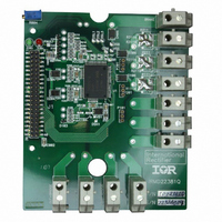
... International Rectifier IRMD22381Q Demo Board For 3-phase / 380V motor drives IR22381Q Demo Board without IGBT Power Module www.irf.com 233 Kansas Street, El Segundo, CA 90245 IRMD2231Q USA ...
Page 2
... Easy to mount heat-sink holes Introduction The IRMD22381Q demo board is an evaluation board for IR22381Q gate driver (see device datasheet for details). IRMD22381Q is designed to drive 3-phase power modules with pin-out compatible to ECONO2-PIM. The board can drive AC or Brushless motors using power modules with up to 25A output current. The board is a flexible solution for different applications and can be customized by means reconfigurable components options. The control signals are 3.3V CMOS compatible ...
Page 3
... Table of figures Figure 1: TOP image of board ...........................................................................................................................4 Figure 2: LED connection ..................................................................................................................................5 Figure 3: Test bench connection .......................................................................................................................8 Figure 7: Bootstrap circuit................................................................................................................................10 Figure 8: Desat external filter ..........................................................................................................................11 Figure 9: -V clamp ..........................................................................................................................................12 s Figure 10: COM below ground protection........................................................................................................13 Figure 11: Collector-Gate current protection ...................................................................................................13 Figure 12: Zener clamp for IGBT gate.............................................................................................................14 www.irf.com IRMD22381Q 2 ...
Page 4
... Voltage feedback provides accurate volt x second measurement. Important Notice IRMD22381Q demo board is supplied with a tentative Bill of Material suitable for a 1200V/10A@100C power module. The BOM presented on page 15 provides a suggestion for the above mentioned power module strongly recommended to customize the demo board to fit the application requirements for the power module that has been chosen ...
Page 5
... BOARD CONNECTORS J1 Connection with the system controller On board there pins connector for the control signals. The driver board uses 26 pins. The remaining pins are for the sensing board (IRCS2277S) that can be connected on top of IRMD22381Q board. HINU/N FAULT/N LINV VSS – RT- ...
Page 6
... At DC+= 330V, DCF≈1.4V. RT+ and RT- RT+ and RT-, thermistor output, are connected to the corresponding RT+, RT- pins of the power module. Note: RT- is starred to Vss at pin 19 of the J1 connector in the IRMD22381Q PCB. VFHx and VFLx Voltage feedback outputs from IRMD22381Q Note: further information about IR22381Q I/Os are described in details in IR22381Q datasheet. ...
Page 7
... The board is fully compatible with the ECONO2-PIM power module. The following table shows the module pin-out. CONNECTION POINTS BETWEEN BOARD AND MODULE www.irf.com CONNECTOR P1 SHU+ 1 SHU CONNECTOR P2 SHV+ 1 SHV CONNECTOR P3 1 SHW bridge V bridge W bridge Phase U Phase V Phase W BRAKE – Brake IGBT drain output RT+ - thermistor positive pin IRMD22381Q traces are both on top and on other bus 6 ...
Page 8
... High side desat input voltage Low side desat input voltage OTHER Fault and Shut Down (or-wired) Brake desat input voltage Brake IGBT gate Low side and logic fixed supply voltage Device V SS DC-SENSE – common low side emitter voltage Table 4: Test points IRMD22381Q W) 7 ...
Page 9
... TEST BENCH CONNECTION IRMD22381Q does NOT provide opto isolation. The following picture shows the recommended connections for board evaluation. Bold lines are equipotential (DC-=Vss=gnd). Low Voltage supply Vdd gnd Controller board Flat cable or direct connection (preferred) via female connector, to provide signals and supply (Vcc=15V typ) www ...
Page 10
... The procedure is totally managed by an integrated FAULT LOGIC block without the controller assistance. Multilevel board solution With the optional shunt resistor the IRMD22381Q driver board can be connected with the IRCS2277S current sensing board through J1 and P1, P2, and P3 connectors. More information is available in IRCS2277S demo board data sheet ...
Page 11
... Figure 4 shows the circuit on board boot boot VCC VCC V S VSS Figure 4: Bootstrap circuit U V C004 C004 * C101 C201 ** C104 C204 * R101 R201 ** R106 R206 U V R103 R203 IRMD22381Q DC boot boot + VGH ** R boot VEH phase VGL VEL W C004 C301 C304 R301 R306 W R303 10 ...
Page 12
... LON brake gate to BR OTHER EXTRA COMPONENTS These components are provided to make IRMD22381Q board as customizable as possible. In many cases the use of the extra components is not necessary. Desat circuit The IR22381Q is able to detect the IGBT desaturation. To reject the noise on the desat pins the IR22381Q have an internal filter of 1µ ...
Page 13
... The following table shows the names of these components on board. DIODE ZENER www.irf.com pin goes below ground out of the device absolute maximum boot boot VCC boot V S VSS structure with Figure 6: -V clamp D104 D204 D304 Z102 Z202 Z302 IRMD22381Q DC boot + VGH ** R boot VEH phase Clamping VGL zener diode VEL 12 ...
Page 14
... The following table shows the names of these components on board. (high side) D (low side) D (brake) D www.irf.com C Vcc COM R GOFF ON COM Vss GATE DRIVER R COM Figure 7: COM below ground protection C101 COM R R006 COM DC ONp Pn R GATE D103 D203 G D105 D205 G D405 G IRMD22381Q OUT W D303 D305 supply B 13 ...
Page 15
... GATE DRIVER high side driver boot low side driver R COM COM Figure 9: Zener clamp for IGBT gate U V Z101 Z201 Z103 Z203 Z403 U V R111 R211 R111A // R211A R111B R211B Vcc decoupling R001 IRMD22381Q V LOAD OUT Z301 Z303 W R311 // R311A // R311B 14 ...
Page 16
... BILL OF MATERIAL The hereafter provided BOMs represent a suggestion based on the IGBT characteristics shown below. www.irf.com IRMD22381Q 15 ...
Page 17
... IRMD22381Q 17 ...
Page 18
... IRMD22381Q 18 ...
Page 19
... IRMD22381Q 19 ...
Page 20
... LAYOUT www.irf.com TOP SILK IRMD22381Q 20 ...
Page 21
... TOP LAYER IRMD22381Q 21 ...
Page 22
... INT1 LAYER IRMD22381Q 22 ...
Page 23
... INT2 LAYER IRMD22381Q 23 ...
Page 24
... BOT LAYER IRMD22381Q 24 ...
Page 25
... WORLD HEADQUARTERS: 233 Kansas Street, El Segundo, California 90245 Tel: (310) 252-7105 www.irf.com BOT SILK http://www.irf.com/ Data and specifications subject to change without notice. IRMD22381Q 5/26/2005 25 ...