EVAL6599-200W STMicroelectronics, EVAL6599-200W Datasheet - Page 15
EVAL6599-200W
Manufacturer Part Number
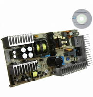
EVAL6599-200W
Description
EVAL BOARD FOR L6599
Manufacturer
STMicroelectronics
Type
Power Factor Correctionr
Specifications of EVAL6599-200W
Main Purpose
AC/DC, Primary Side and PFC
Outputs And Type
4, Isolated
Power - Output
200W
Voltage - Output
24V, 12V, 5V, 3.3V
Current - Output
6A, 5A, 1A, 700mA
Voltage - Input
90 ~ 264VAC
Regulator Topology
Resonant
Frequency - Switching
95kHz
Board Type
Fully Populated
Utilized Ic / Part
L6563, L6599
Input Voltage
90 V to 264 V
Output Voltage
3.3 V to 24 V
Dimensions
132 mm x 265 mm
Product
Power Management Modules
Lead Free Status / RoHS Status
Lead free / RoHS Compliant
For Use With/related Products
L6599
Other names
497-5496


L6599
7
Application information
The L6599 is an advanced double-ended controller specific for resonant half-bridge
topology. In these converters the switches (MOSFETs) of the half-bridge leg are alternately
switched on and OFF (180° out-of-phase) for exactly the same time. This is commonly
referred to as operation at "50 % duty cycle", although the real duty cycle, that is the ratio of
the ON-time of either switch to the switching period, is actually less than 50 %. The reason
is that there is an internally fixed dead-time T
MOSFET and the turn-ON of the other one, where both MOSFETs are OFF. This dead- time
is essential in order for the converter to work correctly: it will ensure soft-switching and
enable high-frequency operation with high efficiency and low EMI emissions.
To perform converter's output voltage regulation the device is able to operate in different
modes
1.
2.
Figure 21. Multi-mode operation
Variable frequency at heavy and medium/light load. A relaxation oscillator (see
"Oscillator" section for more details) generates a symmetrical triangular waveform,
which MOSFETs' switching is locked to. The frequency of this waveform is related to a
current that will be modulated by the feedback circuitry. As a result, the tank circuit
driven by the half-bridge will be stimulated at a frequency dictated by the feedback loop
to keep the output voltage regulated, thus exploiting its frequency-dependent transfer
characteristics.
Burst-mode control with no or very light load. When the load falls below a value, the
converter will enter a controlled intermittent operation, where a series of a few
switching cycles at a nearly fixed frequency are spaced out by long idle periods where
both MOSFETs are in OFF-state. A further load decrease will be translated into longer
idle periods and then in a reduction of the average switching frequency. When the
converter is completely unloaded, the average switching frequency can go down even
to few hundred Hz, thus minimizing magnetizing current losses as well as all frequency-
related losses and making it easier to comply with energy saving recommendations.
(Figure
21), depending on the load conditions:
D
, inserted between the turn-OFF of either
Application information
15/36
Related parts for EVAL6599-200W
Image
Part Number
Description
Manufacturer
Datasheet
Request
R

Part Number:
Description:
EVAL BOARD FOR L6599
Manufacturer:
STMicroelectronics
Datasheet:

Part Number:
Description:
DEMO BOARD FOR L6599
Manufacturer:
STMicroelectronics
Datasheet:

Part Number:
Description:
DEMO BOARD FOR L6599
Manufacturer:
STMicroelectronics
Datasheet:

Part Number:
Description:
STMicroelectronics [RIPPLE-CARRY BINARY COUNTER/DIVIDERS]
Manufacturer:
STMicroelectronics
Datasheet:
Part Number:
Description:
STMicroelectronics [LIQUID-CRYSTAL DISPLAY DRIVERS]
Manufacturer:
STMicroelectronics
Datasheet:

Part Number:
Description:
BOARD EVAL FOR MEMS SENSORS
Manufacturer:
STMicroelectronics
Datasheet:
Part Number:
Description:
NPN TRANSISTOR POWER MODULE
Manufacturer:
STMicroelectronics
Datasheet:
Part Number:
Description:
TURBOSWITCH ULTRA-FAST HIGH VOLTAGE DIODE
Manufacturer:
STMicroelectronics
Datasheet:
Part Number:
Description:
Manufacturer:
STMicroelectronics
Datasheet:
Part Number:
Description:
DIODE / SCR MODULE
Manufacturer:
STMicroelectronics
Datasheet:
Part Number:
Description:
DIODE / SCR MODULE
Manufacturer:
STMicroelectronics
Datasheet:
Part Number:
Description:
Search -----> STE16N100
Manufacturer:
STMicroelectronics
Datasheet: