EVAL6599-200W STMicroelectronics, EVAL6599-200W Datasheet
EVAL6599-200W
Specifications of EVAL6599-200W


Related parts for EVAL6599-200W


EVAL6599-200W Summary of contents
Page 1
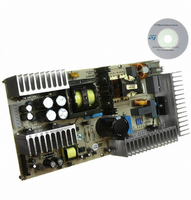
... STMicroelectronics L6599 resonant controller. A further auxiliary flyback converter based on the VIPer12A-E off-line primary switcher completes the architecture. This third block is mainly intended for microprocessor supply and display power management operations. Figure 1. L6599 and L6563 200W evaluation board (EVAL6599-200W) October 2007 Application note Rev 5 AN2393 1/35 www ...
Page 2
Contents Contents 1 Main characteristics and circuit description . . . . . . . . . . . . . . . . . . . . . 4 2 Electrical test results . . . . . . ...
Page 3
... AN2393 List of figures Figure 1. L6599 and L6563 200W evaluation board (EVAL6599-200W Figure 2. PFC pre-regulator electrical diagram . . . . . . . . . . . . . . . . . . . . . . . . . . . . . . . . . . . . . . . . . . 6 Figure 3. Resonant converter electrical diagram . . . . . . . . . . . . . . . . . . . . . . . . . . . . . . . . . . . . . . . . . 7 Figure 4. Auxiliary converter electrical diagram . . . . . . . . . . . . . . . . . . . . . . . . . . . . . . . . . . . . . . . . . . 8 Figure 5. Overall efficiency versus output power at nominal mains voltages Figure 6. Overall efficiency versus output power at several input voltage values . . . . . . . . . . . . . . . 11 Figure 7 ...
Page 4
Main characteristics and circuit description 1 Main characteristics and circuit description The main characteristics of the SMPS are listed below: ● Universal input mains range 264 V ● Output voltages: – 24 V@6 A continuous operation – 12 ...
Page 5
AN2393 changing the frequency according to the feedback signal in order to regulate the output voltages against load and input voltage variations. The main features of the L6599 are a non-linear soft-start, a current protection mode used to program the ...
Page 6
Main characteristics and circuit description Figure 2. PFC pre-regulator electrical diagram 1-2 4-5 6/35 AN2393 ...
Page 7
AN2393 Figure 3. Resonant converter electrical diagram Main characteristics and circuit description 7/35 ...
Page 8
Main characteristics and circuit description Figure 4. Auxiliary converter electrical diagram 8/35 AN2393 ...
Page 9
AN2393 2 Electrical test results 2.1 Efficiency measurements Table 1 and Table 2 of 115 V and 230 V ac and at light load operation, the input power is measured using a Yokogawa WT-210 digital power meter. Particular attention has ...
Page 10
Electrical test results Also at light load output power of about 10% of the maximum level, the overall efficiency is very good, reaching a value better than 79% over the entire input mains voltage range. Figure 6 shows ...
Page 11
AN2393 Figure 6. Overall efficiency versus output power at several input voltage values 95.00% 94.00% 93.00% 92.00% 91.00% 90.00% 89.00% 88.00% 87.00% 86.00% 85.00% 84.00% 83.00% 82.00% 81.00% 80.00% 79.00% 78.00% 77.00% 76.00% 75.00 95.00% 94.00% 93.00% ...
Page 12
Electrical test results while the almost sinusoidal current waveform just allows for an extremely low EMI generation. Figure 8 shows the same waveforms of previous figure, when both the outputs are not loaded. This picture demonstrates the ability of the ...
Page 13
AN2393 Waveform CH3 shows the current flowing into one of the two output diodes for each output voltage (respectively D8A and D10A). Also this current shape is almost a sine wave, whose average value is one half the output current. ...
Page 14
Electrical test results Thus clear that the proposed architecture is really suitable for power supplies operating with strong load variation without any problem related to the load regulation. Figure 12. Load transition (0 - 100%) on +24 V ...
Page 15
AN2393 Table 3. Stand-by consumption V(V) @load(A) 5.08 - 0.018 5.04 - 0.018 4.98 - 0.018 4.92 - 0.018 4.47 - 0.000 Table 4. Stand-by consumption V(V) @load(A) 5.08 - 0.018 5.04 - 0.018 ...
Page 16
Electrical test results side of the figure the very low mean current flowing in the shorted output which is less than 0.3 A. Figure 14. +24 V output short-circuit waveforms Short circuit on +24 V output voltage Ch1: +24 V ...
Page 17
AN2393 3 Thermal tests In order to check the design reliability, a thermal mapping by means Camera was performed. Figure 16 component side, at nominal input voltage. The correlation between measurement points and components is indicated for ...
Page 18
Thermal tests Table 5. Key components temperature at 115 V 18/35 Ambient temperature: 25° C Item (Fe) L4 (Cu D8A D8B D10A D10B C29 C30 C37 C38 ...
Page 19
AN2393 Table 6. Key components temperature at 230 V All other board components work within the temperature limits, assuring a reliable long term operation of the power supply. Note that the temperatures of L4 and T1 have been measured both ...
Page 20
Conducted emission pre-compliance test 4 Conducted emission pre-compliance test The limits indicated on both diagrams at 115 V specifications. The measurements have been taken in Quasi Peak detection mode. Figure 18. CE quasi peak measurement at 115 V Figure 19. ...
Page 21
AN2393 5 Bill of materials Table 7. Bill of materials Item Part type/value C2 100 nF-X2 C3 330 nF-X2 C4 680 nF-X2 C5 330 nF/630 V C6 680 nF/630 V C7 470 nF/630 V C8 220 µF/450 V C9 2nF2-Y1 ...
Page 22
... BZV55-C Series Zener Diode Peak Clamp Transil AN2393 Supplier RIFA-EVOX Rubycon Rubycon Rubycon BC Components BC Components Rubycon BC Components Rubycon Rubycon Rubycon Rubycon Rubycon Rubycon BC Components BC Components BC Components BC Components Rubycon BC Components BC Components BC Components Vishay Shindengen STMicroelectronics Vishay Vishay Vishay STMicroelectronics Vishay STMicroelectronics Vishay Vishay Vishay STMicroelectronics ...
Page 23
... SMD Standard Film RES 1 0ppm/°C Bill of materials Supplier STMicroelectronics STMicroelectronics Vishay Vishay Vishay Vishay Vishay Vishay Vishay Wickmann Molex Molex AMP TDK Delta Delta Coilcraft Coilcraft Coilcraft Coilcraft STMicroelectronics STMicroelectronics STMicroelectronics STMicroelectronics STMicroelectronics STMicroelectronics STMicroelectronics STMicroelectronics STMicroelectronics BC Components Epcos BC Components BC Components BC Components BC Components 23/35 ...
Page 24
Bill of materials Table 7. Bill of materials (continued) Item Part type/value R7 2M2 R8 680 kΩ R9 2M2 R10 100 kΩ R11 15 kΩ R13 56 kΩ R14 1k5 R16 5k1 R17 15 kΩ R18 6R8 R19 1K0 R20 ...
Page 25
... CTR Selection Optocoupler Bill of materials Supplier BC Components BC Components BC Components BC Components BC Components BC Components BC Components BC Components BC Components BC Components BC Components BC Components BC Components BC Components BC Components BC Components BC Components BC Components BC Components BC Components BC Components BC Components BC Components BC Components BC Components BC Components BC Components BC Components BC Components BC Components Delta Delta STMicroelectronics STMicroelectronics Infineon 25/35 ...
Page 26
... The auxiliary winding is not used in this design, but is foreseen for another application 26/35 Description TO92 Programmable Shunt Voltage Regulator Low Power Off Line SMPS Primary Switcher 63-125% CTR Selection Optocoupler TO92 Programmable Shunt Voltage Regulator 63-125% CTR Selection Optocoupler 4-5 Primary 1-2 AN2393 Supplier STMicroelectronics STMicroelectronics Infineon STMicroelectronics Infineon Note 1) 12 Auxiliary 8 ...
Page 27
AN2393 Table 8. PFC coil winding characteristics Start pins End pins and 5 1 and 2 6.2 Mechanical aspect and pin numbering ● Maximum height from PCB ● Cut pins and 11 ● ...
Page 28
Resonant power transformer specification 7.1 Electrical characteristics and mechanical aspect ● Converter topology: half-bridge, resonant ● Core type: ER49 - PC44 or equivalent ● Typical operating frequency: 100 kHz Primary inductance: 585 µH ±10% @1 kHz - 0.25 V (see ...
Page 29
AN2393 Figure 23. Resonant transformer electrical diagram Table 10. Resonant transformer winding characteristics Pins Winding Primary Sec Sec Sec Sec ...
Page 30
Auxiliary flyback power transformer 8 Auxiliary flyback power transformer ● Application type: Consumer, home appliance ● Transformer type: Open ● Winding type: Layer ● Coil former: Horizontal type, 4+5 pins ● Maximum temperature rise: 45° C ● Maximum operating ambient ...
Page 31
AN2393 Figure 26. Auxiliary transformer winding position on coil former Coil Former Table 11. Auxiliary transformer winding characteristics Pins Start - End 4-5 2-1 8-10 6-7 Note: Manufacturer: DELTA ELECTRONICS - Part number: 86A-6079-R 3.3 V/5 V Auxiliary Primary Winding ...
Page 32
Reference design board layout 9 Reference design board layout Figure 27. Copper tracks 32/35 AN2393 ...
Page 33
AN2393 Figure 28. Thru-hole component placing and top silk screen Figure 29. SMT component placing and bottom silk screen Reference design board layout 33/35 ...
Page 34
Revision history 10 Revision history Table 12. Document revision history Date 02-Aug-2006 08-Sep-2006 25-Jan-2007 23-Apr-2007 25-Oct-2007 34/35 Revision 1 Initial release 2 Figure 2. modified 3 Minor text change – Cross references updated 4 – Table 7: Bill of materials ...
Page 35
... AN2393 Information in this document is provided solely in connection with ST products. STMicroelectronics NV and its subsidiaries (“ST”) reserve the right to make changes, corrections, modifications or improvements, to this document, and the products and services described herein at any time, without notice. All ST products are sold pursuant to ST’s terms and conditions of sale. ...