RLINK-ST STMicroelectronics, RLINK-ST Datasheet - Page 50
RLINK-ST
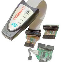
Manufacturer Part Number
RLINK-ST
Description
ADAPTER USB-JTAG FOR DK3300
Manufacturer
STMicroelectronics
Specifications of RLINK-ST
Accessory Type
Cable - ISP (In-System Programming)
For Use With/related Products
ST Micro - DK3300, DK3400
Lead Free Status / RoHS Status
Lead free / RoHS Compliant
Other names
497-4831


Electrical parameters
4.3.5
50/78
I/O port pin characteristics
General characteristics
Subject to general operating conditions for V
unused pins must be kept at a fixed voltage: using the output mode of the I/O for example or
an external pull-up or pull-down resistor.
Table 29.
Notes:
1. Data based on characterization results, not tested in production.
2. Hysteresis voltage between Schmitt trigger switching levels. Based on characterization results, not tested.
3. When the current limitation is not possible, the V
4. Leakage could be higher than max. if negative current is injected on adjacent pins.
5. The R
ΣI
Symbol
I
INJ(PIN)
INJ(PIN)
V
V
R
R
refer to I
induced by V
I
C
V
V
V
V
V
V
I
PU
3)
lkg
hys
hys
PU
PD
IH
IH
IH
IO
IL
IL
IL
and I
PU
INJ(PIN)
PD
Input low level voltage
Input high level voltage
Schmitt trigger voltage hysteresis
2)
Input low level voltage
Input high level voltage
Schmitt trigger voltage hysteresis
2)
Input low level voltage
Input high level voltage
Injected Current on any I/O pin
Total injected current (sum of all
I/O and control pins)
Input leakage current
Weak pull-up equivalent
resistor
Weak pull-down equivalent
resistor
I/O pin capacitance
pull-up and R
current characteristics described in
I/O static characteristics
IN
<V
specification. A positive injection is induced by V
5)
5)
SS
. Refer to
Parameter
PD
pull-down equivalent resistor are based on a resistive transistor (corresponding
Section 4.2 on page 34
4)
1)
1)
1)
1)
1)
1)
Figure 18
IN
CMOS ports
P0.15 WAKEUP
TTL ports
V
V
V
SS
IN
IN
absolute maximum rating must be respected, otherwise
33
=
=
Conditions
≤
V
V
V
for more details.
and T
SS
33
IN
≤
to
V
Figure
33
A
unless otherwise specified. All
IN
>V
19).
33
while a negative injection is
0.7V
Min
110
110
2.0
2
33
1.35
Typ
150
150
0.8
0.9
0.4
5
0.3V
Max
± 25
700
700
0.8
0.8
± 4
±1
33
STR71xF
Unit
mA
µA
kΩ
kΩ
pF
V
V
V
V
V
Related parts for RLINK-ST
Image
Part Number
Description
Manufacturer
Datasheet
Request
R

Part Number:
Description:
STMicroelectronics [RIPPLE-CARRY BINARY COUNTER/DIVIDERS]
Manufacturer:
STMicroelectronics
Datasheet:
Part Number:
Description:
STMicroelectronics [LIQUID-CRYSTAL DISPLAY DRIVERS]
Manufacturer:
STMicroelectronics
Datasheet:

Part Number:
Description:
BOARD EVAL FOR MEMS SENSORS
Manufacturer:
STMicroelectronics
Datasheet:
Part Number:
Description:
NPN TRANSISTOR POWER MODULE
Manufacturer:
STMicroelectronics
Datasheet:
Part Number:
Description:
TURBOSWITCH ULTRA-FAST HIGH VOLTAGE DIODE
Manufacturer:
STMicroelectronics
Datasheet:
Part Number:
Description:
Manufacturer:
STMicroelectronics
Datasheet:
Part Number:
Description:
DIODE / SCR MODULE
Manufacturer:
STMicroelectronics
Datasheet:
Part Number:
Description:
DIODE / SCR MODULE
Manufacturer:
STMicroelectronics
Datasheet:
Part Number:
Description:
Search -----> STE16N100
Manufacturer:
STMicroelectronics
Datasheet:
Part Number:
Description:
Search ---> STE53NA50
Manufacturer:
STMicroelectronics
Datasheet:
Part Number:
Description:
NPN Transistor Power Module
Manufacturer:
STMicroelectronics
Datasheet:
Part Number:
Description:
DIODE / SCR MODULE
Manufacturer:
STMicroelectronics
Datasheet: