27100 Parallax Inc, 27100 Datasheet - Page 9
27100
Manufacturer Part Number
27100
Description
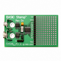
BASIC STAMP REV DX MODULE
Manufacturer
Parallax Inc
Type
Microcontrollerr
Datasheet
1.27100.pdf
(23 pages)
Specifications of 27100
Contents
Board
Product
Microcontroller Basic Stamps
Operating Supply Voltage
5 to 15 V
Board Size
63.5 mm x 38.1 mm x 12.7 mm
For Use With/related Products
BASIC Stamp®
Lead Free Status / RoHS Status
Lead free / RoHS Compliant
Available stocks
Company
Part Number
Manufacturer
Quantity
Price

Part Number:
271000-51300730
Manufacturer:
DENSO
Quantity:
20 000


STAMP FAQS
How many I/O pins does the BASIC Stamp have?
What can I use the I/O pins for?
Can the I/O pins be used to control relays, solenoids and other similar devices?
Can I control LEDs with the I/O pins?
How much current can the I/O pins handle?
What is the input impedance of the BASIC Stamp’s I/O pins?
How fast does the BASIC Stamp execute its PBASIC code?
Last Revised On: 7/21/00
The BASIC Stamp I has 8 I/O pins while the BASIC Stamp II, BASIC STAMP IIe and BASIC Stamp IIsx has
16 I/O pins plus 2 special serial port pins (1 input, 1 output).
The BASIC Stamp’s I/O pins are perfectly suited for digital input and output with TTL/CMOS level (0 to 5 volt)
signals. However, you can use some special commands and techniques to input and output limited analog signals.
For example, the RCTIME and PWM commands can be used to read a variable resistance or output a variable
voltage from 0 to 5 volts. The I/O pins can not be used to read analog voltages by themselves, however, but this
can be done by interfacing the I/O pins to an A to D converter chip.
Yes, however, due to the demanding current and voltage requirements of some of these components, driver circuitry
will need to be used to properly isolate the I/O pins from harmful effects. For examples of this, refer to BASIC
Stamp I Application Note #6 and BASIC Stamp Article #6, “Silicon Steroids for Stamps”.
Yes. Simply use a 470 ohm resister in series with the LED to limit the current draw through the I/O pin (see “How
much current can the I/O pins handle?”). Also, keep in mind that most LEDs require a lot of current in relation to
what the BASIC Stamp can provide. If you attach and power 3 or more LEDs at one time from the BASIC
Stamp’s I/O pins, you are likely to see flaky and unpredictable results caused by voltage sag, I/O pin damage
and/or hardware resets. Driver circuitry or low current LEDs will need to be used if you require such an application.
On the BASIC Stamp I and BASIC Stamp II, each I/O pin is capable of sourcing 20 mA and sinking 25 mA. The
total across all I/O pins should not exceed 40 mA source or 50 mA sink at any given time, however. One
exception to this rule exists with the BS2-IC. If the BS2-IC is powered by an external 5-volt regulator capable of
delivering at least 100 mA, the total across each group of 8 I/O pins (0 - 7 and 8 - 15) can reach 40 mA source or
50 mA sink providing a total of 80 mA source or 100 mA sink overall. The BASIC Stamp IIsx’s I/O pins can
source and sink 30 mA, and the total across all I/O pins should not exceed 150 mA.
Approximately 1 Meg Ohm.
On average, the BASIC Stamp I executes 2000 instructions per second, the BASIC Stamp II executes 4000
instructions per second, the BASIC Stamp IIe executes apx 3800 instructions per second and the BASIC Stamp
IIsx executes 10000 instructions per second. This is only an estimate as the true execution speed depends upon
many factors including, the particular set of instructions used and the type of arguments provided to the instructions.
Some instructions execute at a much faster rate while others, especially those that have to deal with external signal
measurement or specific protocol speeds, will execute much slower.
PROGRAMMING INFORMATION
Page: 9
Related parts for 27100
Image
Part Number
Description
Manufacturer
Datasheet
Request
R


Part Number:
Description:
Microcontroller Modules & Accessories DISCONTINUED BY PARALLAX
Manufacturer:
Parallax Inc

Part Number:
Description:
BOOK UNDERSTANDING SIGNALS
Manufacturer:
Parallax Inc
Datasheet:


Part Number:
Description:
COMPETITION RING FOR SUMOBOT
Manufacturer:
Parallax Inc
Datasheet:


Part Number:
Description:
TEXT INFRARED REMOTE FOR BOE-BOT
Manufacturer:
Parallax Inc
Datasheet:
Part Number:
Description:
BOARD EXPERIMENT+LCD NX-1000
Manufacturer:
Parallax Inc
Datasheet:

Part Number:
Description:
CONTROLLER 16SERVO MOTOR CONTROL
Manufacturer:
Parallax Inc
Datasheet:

Part Number:
Description:
BASIC STAMP LOGIC ANALYZER
Manufacturer:
Parallax Inc
Datasheet:

Part Number:
Description:
IC MCU 2K FLASH 50MHZ SO-18
Manufacturer:
Parallax Inc
Datasheet: