27100 Parallax Inc, 27100 Datasheet - Page 16
27100
Manufacturer Part Number
27100
Description
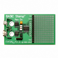
BASIC STAMP REV DX MODULE
Manufacturer
Parallax Inc
Type
Microcontrollerr
Datasheet
1.27100.pdf
(23 pages)
Specifications of 27100
Contents
Board
Product
Microcontroller Basic Stamps
Operating Supply Voltage
5 to 15 V
Board Size
63.5 mm x 38.1 mm x 12.7 mm
For Use With/related Products
BASIC Stamp®
Lead Free Status / RoHS Status
Lead free / RoHS Compliant
Available stocks
Company
Part Number
Manufacturer
Quantity
Price

Part Number:
271000-51300730
Manufacturer:
DENSO
Quantity:
20 000


STAMP FAQS
How do I set an I/O pin to input or output mode?
Last Revised On: 7/21/00
There are many ways to set the I/O pin directions. The most readable and intuitive method is to use the INPUT and
OUTPUT commands. For example:
will set I/O pin 5 to an input and I/O pin 6 to an output. By default, upon reset or startup, all I/O pins are inputs,
thus only the second line of code above is really necessary.
Another method for setting the pin directions is to use the predefined variable DIRS or any one of its derivatives.
The following code is functionally equivalent to the first example:
DIR0 through DIR15 (or DIR7 on the BASIC Stamp I) are bit variables which control the direction of the
corresponding I/O pin. DIRS is a 16-bit variable (or 8-bit variable on the BASIC Stamp I) in which each bit
represents the direction of the corresponding I/O pin. A ‘1’ bit means output and a ‘0’ bit means input. The
advantage of this method of declaring pin directions is that multiple pin directions can be defined at once:
The above line of code defines I/O pins 7, 6, 4 and 0 as inputs and 5, 3, 2 and 1 as outputs. Review the BASIC
Stamp manual for more examples of this.
INPUT 5
OUTPUT 6
DIR5 = 0
DIR6 = 1
DIRS = %00101110
PROGRAMMING INFORMATION
Page: 16
Related parts for 27100
Image
Part Number
Description
Manufacturer
Datasheet
Request
R


Part Number:
Description:
Microcontroller Modules & Accessories DISCONTINUED BY PARALLAX
Manufacturer:
Parallax Inc

Part Number:
Description:
BOOK UNDERSTANDING SIGNALS
Manufacturer:
Parallax Inc
Datasheet:


Part Number:
Description:
COMPETITION RING FOR SUMOBOT
Manufacturer:
Parallax Inc
Datasheet:


Part Number:
Description:
TEXT INFRARED REMOTE FOR BOE-BOT
Manufacturer:
Parallax Inc
Datasheet:
Part Number:
Description:
BOARD EXPERIMENT+LCD NX-1000
Manufacturer:
Parallax Inc
Datasheet:

Part Number:
Description:
CONTROLLER 16SERVO MOTOR CONTROL
Manufacturer:
Parallax Inc
Datasheet:

Part Number:
Description:
BASIC STAMP LOGIC ANALYZER
Manufacturer:
Parallax Inc
Datasheet:

Part Number:
Description:
IC MCU 2K FLASH 50MHZ SO-18
Manufacturer:
Parallax Inc
Datasheet: