EVAL-AD5390EB Analog Devices Inc, EVAL-AD5390EB Datasheet - Page 5
EVAL-AD5390EB
Manufacturer Part Number
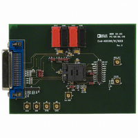
EVAL-AD5390EB
Description
BOARD EVAL FOR AD5390
Manufacturer
Analog Devices Inc
Specifications of EVAL-AD5390EB
Number Of Dac's
16
Number Of Bits
14
Outputs And Type
16, Single Ended
Sampling Rate (per Second)
125k
Data Interface
Serial
Settling Time
8µs
Dac Type
Voltage
Voltage Supply Source
Single
Operating Temperature
-40°C ~ 85°C
Utilized Ic / Part
AD5390
Lead Free Status / RoHS Status
Contains lead / RoHS non-compliant


EVALUATION BOARD SOFTWARE
SOFTWARE INSTALLATION
The EVAL-AD5390/91/92EB evaluation kit includes self-
installing software on CD-ROM. If the setup file does not run
automatically, you can run setup.exe from the CD-ROM.
The evaluation board software is compatible with Windows® 95
to Windows XP. Ensure that the Centronics cable connects the
PC to the EVAL-AD5390/91/92EB evaluation board.
1.
2.
The AD5390/91/92 Evaluation Software dialog box is
displayed. Figure 2 shows the drop-down menus (File, Printer
Port, Dac, Register, and Help).
LOAD DAC CHANNELS
The Dac menu allows user control of the 8/16 DAC channels, as
well as other functions such as hardware reset of the DAC
channels and clearing the outputs.
To load DAC channels:
1.
2.
3.
4.
On the Analog Devices menu, select AD539x Evaluation
Software.
At the prompt, select the relevant device.
On the Dac menu, select Load/Calibrate Dac Channel.
The Load/Calibrate Dac Outputs dialog box is displayed.
In the Enter Channel box, enter the channel selection.
In the Enter Data (Hex) box, type a DAC code to load to
the selected channel.
Press Enter on your keyboard after entering data.
Figure 2.
Figure 3.
Rev. 0 | Page 5 of 12
5.
CHANNEL CALIBRATION
1.
2.
3.
4.
5.
6.
You can also manually program the gain and offset registers.
1.
2.
and the B Register. Click the Toggle Selected Register for
output button to toggle between the two registers.
Click Calibrate Channel to display the Channel
Calibration dialog box.
Type the reference value in the Enter Vref(+) Value (V)
box.
Load full scale and measure the output voltage on the
relevant channel.
Input this value in the appropriate field in the dialog box.
Load zero scale and again enter the measured value in the
appropriate field.
Click Calibrate to calibrate the device to the required
output voltage.
Click Manually Program Calibration Registers. The
Program m and c Registers dialog box is displayed.
Type values for the gain and offset registers and click the
accompanying buttons to program the registers.
Each DAC has two associated data registers, the A Register
Figure 4.
Figure 5.
EVAL-AD5390/91/92EB
Related parts for EVAL-AD5390EB
Image
Part Number
Description
Manufacturer
Datasheet
Request
R

Part Number:
Description:
ENERCHIP CC EVAL KIT
Manufacturer:
Cymbet Corporation
Datasheet:

Part Number:
Description:
BOARD EVAL FOR AD976
Manufacturer:
Analog Devices Inc
Datasheet:

Part Number:
Description:
BOARD EVAL FOR ADXL345
Manufacturer:
Analog Devices Inc
Datasheet:

Part Number:
Description:
ENERCHIP CC SEH EVAL KIT
Manufacturer:
Cymbet Corporation
Datasheet:

Part Number:
Description:
ENERCHIP EP ENERGY HARVEST EVAL
Manufacturer:
Cymbet Corporation
Datasheet:

Part Number:
Description:
EVAL BOARD FOR TW6864-LB2-GR
Manufacturer:
Intersil
Datasheet:
Part Number:
Description:
EVAL BOARD FOR TW8816-LB3-GR
Manufacturer:
Intersil
Datasheet:
Part Number:
Description:
EVAL BOARD FOR TW8817-TA3-GRS
Manufacturer:
Intersil
Datasheet:

Part Number:
Description:
EVALUATION MODULE FOR ADUM4160
Manufacturer:
Analog Devices Inc
Datasheet:

Part Number:
Description:
BOARD EVALUATION ADCMP581BCP
Manufacturer:
Analog Devices Inc
Datasheet:
Part Number:
Description:
BOARD EVALUATION ADM1041
Manufacturer:
Analog Devices Inc
Datasheet:

Part Number:
Description:
EVAL BOARD FOR STM32F107VCT
Manufacturer:
STMicroelectronics
Datasheet:
Part Number:
Description:
BOARD EVAL FOR AD1954
Manufacturer:
Analog Devices Inc
Datasheet:
Part Number:
Description:
BOARD EVAL FOR AD1955
Manufacturer:
Analog Devices Inc
Datasheet:

Part Number:
Description:
BOARD EVAL FOR AD7655
Manufacturer:
Analog Devices Inc
Datasheet: