EVAL-AD1871EB Analog Devices Inc, EVAL-AD1871EB Datasheet - Page 18
EVAL-AD1871EB
Manufacturer Part Number
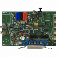
EVAL-AD1871EB
Description
BOARD EVAL FOR AD1871
Manufacturer
Analog Devices Inc
Datasheet
1.AD1871YRSZ.pdf
(28 pages)
Specifications of EVAL-AD1871EB
Lead Free Status / RoHS Status
Contains lead / RoHS non-compliant


AD1871
I
In I
placed in the second BCLK period following the transition of
the LRCLK. A high-to-low transition of the LRCLK signifies
LJ Mode
In LJ Mode, the data is left-justified, MSB first, with the MSB
placed in the first BCLK period following the transition of the
LRCLK. A high-to-low transition of the LRCLK signifies the
RJ Mode
In RJ Mode, the data is right-justified, LSB last, with the
LSB placed in the last BCLK period preceding the transition
of the LRCLK. A high-to-low transition of the LRCLK signifies
DSP Mode
In DSP Mode, the LRCLK signal becomes a frame sync signal
that pulses high for the BCLK period prior to the MSB (or in
the BCLK period of the previous LSB–32 bits). The data is left-
justified, MSB first, with the MSB placed in the BCLK period
following the LRCLK pulse (see Figure 15).
2
S Mode
LRCLK
LRCLK
LRCLK
LRCLK
DOUT
BCLK
DOUT
BCLK
DOUT
BCLK
2
DOUT
BCLK
S Mode, the data is left-justified, MSB first, with the MSB
LSB
MSB
MSB
MSB– 1
MSB
MSB– 1
MSB– 2
MSB–1
MSB– 2
LEFT CHANNEL
MSB
LSB+2
LEFT CHANNEL
LSB+2 LSB+1
LEFT CHANNEL
MSB–1
LEFT CHANNEL
LSB+2 LSB+1
LSB+1
MSB–2
LSB
LSB
LSB
Figure 14. Right-Justified Mode
Figure 13. Left-Justified Mode
Figure 15. DSP Mode
Figure 12. I
LSB+2 LSB+1
–18–
LSB
MSB
2
S Mode
the beginning of the left channel data transfer, while a low-to-
high transition on the LRCLK signifies the beginning of the
right channel data transfer (see Figure 12).
beginning of the right channel data transfer, while a low-to-high
transition on the LRCLK signifies the beginning of the left
channel data transfer (see Figure 13).
the beginning of the right channel data transfer, while a low-to-
high transition on the LRCLK signifies the beginning of the left
channel data transfer (see Figure 14).
In I
data word-width between the AD1871 and the controller are not
catastrophic since the MSBs are guaranteed to be transferred.
There may, however, be a slight reduction in performance
depending on the scale of the mismatch. In RJ Mode, however,
differences in word-width between the AD1871 and controller
have a catastrophic effect on signal performance as the MSBs
of each sample may be lost due to the mismatch.
MSB
MSB– 1
2
MSB
S and LJ Modes, since the data is left-justified, differences in
MSB– 1
MSB– 2
MSB–1
MSB– 2
RIGHT CHANNEL
RIGHT CHANNEL
RIGHT CHANNEL
MSB
LSB+2
LSB+2 LSB+1
RIGHT CHANNEL
LSB+2 LSB+1
MSB–1
LSB+1
MSB–2
LSB
LSB
LSB
LSB+2 LSB+1
LSB
MSB
MSB
MSB
MSB–1
MSB– 1
REV. 0
Related parts for EVAL-AD1871EB
Image
Part Number
Description
Manufacturer
Datasheet
Request
R

Part Number:
Description:
ENERCHIP CC EVAL KIT
Manufacturer:
Cymbet Corporation
Datasheet:

Part Number:
Description:
BOARD EVAL FOR AD976
Manufacturer:
Analog Devices Inc
Datasheet:

Part Number:
Description:
BOARD EVAL FOR ADXL345
Manufacturer:
Analog Devices Inc
Datasheet:

Part Number:
Description:
ENERCHIP CC SEH EVAL KIT
Manufacturer:
Cymbet Corporation
Datasheet:

Part Number:
Description:
ENERCHIP EP ENERGY HARVEST EVAL
Manufacturer:
Cymbet Corporation
Datasheet:

Part Number:
Description:
EVAL BOARD FOR TW6864-LB2-GR
Manufacturer:
Intersil
Datasheet:
Part Number:
Description:
EVAL BOARD FOR TW8816-LB3-GR
Manufacturer:
Intersil
Datasheet:
Part Number:
Description:
EVAL BOARD FOR TW8817-TA3-GRS
Manufacturer:
Intersil
Datasheet:

Part Number:
Description:
EVALUATION MODULE FOR ADUM4160
Manufacturer:
Analog Devices Inc
Datasheet:

Part Number:
Description:
BOARD EVALUATION ADCMP581BCP
Manufacturer:
Analog Devices Inc
Datasheet:
Part Number:
Description:
BOARD EVALUATION ADM1041
Manufacturer:
Analog Devices Inc
Datasheet:

Part Number:
Description:
EVAL BOARD FOR STM32F107VCT
Manufacturer:
STMicroelectronics
Datasheet:
Part Number:
Description:
BOARD EVAL FOR AD1954
Manufacturer:
Analog Devices Inc
Datasheet:
Part Number:
Description:
BOARD EVAL FOR AD1955
Manufacturer:
Analog Devices Inc
Datasheet:

Part Number:
Description:
BOARD EVAL FOR AD7655
Manufacturer:
Analog Devices Inc
Datasheet: