MA300012 Microchip Technology, MA300012 Datasheet - Page 30
MA300012
Manufacturer Part Number
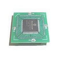
MA300012
Description
MODULE DSPIC30F SAMPLE 64QFP
Manufacturer
Microchip Technology
Specifications of MA300012
Module/board Type
dsPIC30F Plug-in Module
Lead Free Status / RoHS Status
Lead free / RoHS Compliant
For Use With/related Products
DM240001
Lead Free Status / RoHS Status
Lead free / RoHS Compliant, Lead free / RoHS Compliant


dsPIC30F
9.3.2
The PWM time base is provided by a 15-bit timer with
a prescaler and postscaler. The PWM time base can be
configured for four different modes of operation:
• Free Running mode
• Single-Shot mode
• Continuous Up/Down Count mode
• Continuous Up/Down Count mode with interrupts
TABLE 9-1:
9.4
Quadrature encoders (also referred to as Incremental
encoders or Optical encoders) are used in position and
speed
Quadrature encoders enable closed loop control of
many motor control applications, such as Switched
Reluctance (SR) motor and AC Induction Motor
(ACIM).
Typically, three outputs, termed: Phase A, Phase B and
INDEX, provide information that can be decoded to
provide information on the movement of the motor shaft
including distance and direction.
A Quadrature Decoder captures the phase signals and
index pulse and converts the information into a numeric
count of the position pulses. Generally, the count will
increment when the shaft is rotating one direction and
decrement when the shaft is rotating in the other
direction.
DS70043F-page 28
33 ns (30 MHz)
33 ns (30 MHz)
50 ns (20 MHz)
50 ns (20 MHz)
100 ns (10 MHz)
100 ns (10 MHz)
200 ns (5 MHz)
200 ns (5 MHz)
* PWM frequencies will be 1/2 the value indicated for center aligned operation.
for double-updates
detection
QEI Module
T
CY
PWM TIME BASE
(F
CY
EXAMPLE PWM FREQUENCIES AND RESOLUTIONS, 1:1 PRESCALER
)
of
rotating
motion
PTPER Value
0x7FFF
0x03FF
0x7FFF
0x01FF
0x7FFF
0x00FF
0x7FFF
0x007F
systems.
The Up/Down Counting modes support center aligned
PWM generation. The Single-Shot mode allows the
PWM module to support pulse control of certain
Electronically Commutated Motors (ECMs).
Table 9-1 lists the frequencies and resolutions that can
be attained as a function of the dsPIC30F device
instruction cycle frequency.
The QEI module (Figure 9-3) includes:
• Three input pins for two-phase signals and index
• Programmable digital noise filters on inputs
• Quadrature decoder providing counter pulses and
• 16-bit up/down position counter
• Count direction status
• X2 and X4 count resolution
• Two modes of position counter reset
• General Purpose16-bit Timer/Counter mode
• Interrupts generated by QEI or counter events
PWM Resolution
pulse
count direction
16 bits
16 bits
10 bits
16 bits
16 bits
11 bits
9 bits
8 bits
© 2005 Microchip Technology Inc.
PWM Frequency*
29.3 KHz
39.1 KHz
39.1 KHz
39.1 KHz
915 Hz
610 Hz
153 Hz
305 Hz
Related parts for MA300012
Image
Part Number
Description
Manufacturer
Datasheet
Request
R

Part Number:
Description:
Manufacturer:
Microchip Technology Inc.
Datasheet:
Part Number:
Description:
Manufacturer:
Microchip Technology Inc.
Datasheet:
Part Number:
Description:
Manufacturer:
Microchip Technology Inc.
Datasheet:
Part Number:
Description:
Manufacturer:
Microchip Technology Inc.
Datasheet:
Part Number:
Description:
Manufacturer:
Microchip Technology Inc.
Datasheet:
Part Number:
Description:
Manufacturer:
Microchip Technology Inc.
Datasheet:
Part Number:
Description:
Manufacturer:
Microchip Technology Inc.
Datasheet:
Part Number:
Description:
Manufacturer:
Microchip Technology Inc.
Datasheet: