DM163010 Microchip Technology, DM163010 Datasheet - Page 44
DM163010
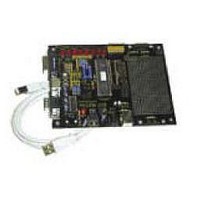
Manufacturer Part Number
DM163010
Description
BOARD DEMO PICDEM USB
Manufacturer
Microchip Technology
Datasheet
1.DM163010.pdf
(80 pages)
Specifications of DM163010
Processor To Be Evaluated
PlC16C745/765
Interface Type
USB
Lead Free Status / RoHS Status
Lead free / RoHS Compliant
Lead Free Status / RoHS Status
Lead free / RoHS Compliant, Lead free / RoHS Compliant


PICDEM™ USB User’s Guide
4.3
DS41174A-page 40
Interrupt Structure Concerns
4.3.1
4.3.2
4.3.3
4.3.4
InitUSB enables the USB interrupt so enumeration can begin. The actual
enumeration process occurs in the background, driven by the host and Inter-
rupt Service Routine. Macro ConfiguredUSB waits until the device is in the
CONFIGURED state. The time required to enumerate is completely depen-
dent on the host and bus loading.
Processor Resources
Most of the USB processing occurs via the interrupt and thus, is invisible to
the application. However, it still consumes processor resources. These
include ROM, RAM, Common RAM, Stack Levels, and Processor Cycles.
This section attempts to quantify the impact on each of these resources and
shows ways to avoid conflicts.
These considerations should be taken into account if you write your own Inter-
rupt Service Routine: Save W, STATUS, FSR, and PCLATH, which are the file
registers that may be corrupted by servicing the USB interrupt.
The file usb_main.asm provides a skeleton ISR, which does this for you, and
includes tests for each of the possible ISR bits. This provides a good starting
point if you haven’t already written your own.
Stack Levels
The hardware stack on the PICmicro MCU is only eight levels deep. There-
fore, the worst case call between the application and ISR can only be eight
levels. The enumeration process requires four levels, so it’s best if the main
application inhibits processing until enumeration is complete. Configure-
dUSB is a macro that waits until the enumeration process is complete for
exactly this purpose. This macro does this by testing the lower two bits of
USWSTAT (0x197).
ROM
The code required to support the USB interrupt, including Chapter 9 interface
calls, but excluding the descriptor tables is about 1 kW. The descriptor and
string descriptor tables can each require an additional 256W. The location of
these descriptors is not restricted, and the linker script may be edited to con-
trol the placement of each descriptor’s part. See the Strings and Descriptors
sections in the linker script.
RAM
With the exception of Common RAM discussed below, servicing the USB
interrupt requires ~40 bytes of RAM in Bank 2. This leaves all the General
Purpose RAM in Bank 0 and Bank 1, while leaving half of Bank 2 available for
your application.
©
2001 Microchip Technology Inc.
Related parts for DM163010
Image
Part Number
Description
Manufacturer
Datasheet
Request
R

Part Number:
Description:
Manufacturer:
Microchip Technology Inc.
Datasheet:
Part Number:
Description:
Manufacturer:
Microchip Technology Inc.
Datasheet:
Part Number:
Description:
Manufacturer:
Microchip Technology Inc.
Datasheet:
Part Number:
Description:
Manufacturer:
Microchip Technology Inc.
Datasheet:
Part Number:
Description:
Manufacturer:
Microchip Technology Inc.
Datasheet:
Part Number:
Description:
Manufacturer:
Microchip Technology Inc.
Datasheet:
Part Number:
Description:
Manufacturer:
Microchip Technology Inc.
Datasheet:
Part Number:
Description:
Manufacturer:
Microchip Technology Inc.
Datasheet: