DM163010 Microchip Technology, DM163010 Datasheet - Page 19
DM163010
Manufacturer Part Number
DM163010
Description
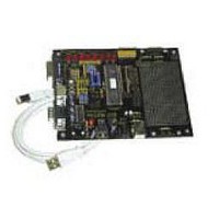
BOARD DEMO PICDEM USB
Manufacturer
Microchip Technology
Datasheet
1.DM163010.pdf
(80 pages)
Specifications of DM163010
Processor To Be Evaluated
PlC16C745/765
Interface Type
USB
Lead Free Status / RoHS Status
Lead free / RoHS Compliant
Lead Free Status / RoHS Status
Lead free / RoHS Compliant, Lead free / RoHS Compliant


©
2001 Microchip Technology Inc.
2.1.4
2.1.5
Gamepad Firmware
The firmware has four functions. Each function either returns one piece of
Table 2.1: Gameport Firmware
Gamepad Report Descriptor
The report descriptor used in this example is for a gamepad with 6 buttons.
voltage level is not symmetrical around 2.5 volts. You would expect the center
position of the D-pad’s x-axis, for instance, to output 2.5 volts, the left position
to output 0 volts and the right position to output 5 volts. Ideally it would, but
the circuitry in the gamepad is very simple; besides, this symmetry is not
needed. All that is needed is a lower voltage input into the PICmicro MCU
when the pad is pressed one direction from center, and a higher voltage input
when the pad is pressed in the other direction from center. The circuitry found
on the PICDEM™ USB board amplifies the differences in voltages between
these three positions and therefore, gives three very distinct analog-to-digital
readings.
information concerning the gameport status, or initiates the gameport regis-
ters. Refer to Table 2.1.
The minimum and maximum report values for the axis are set to 0 - 255. This
is to be used with Windows. Some versions don’t seem to handle a range of
-127 to 127. The -127 value is translated to 255 and causes extreme move-
ment to the right. The range selected works correctly on Windows and on
Macintosh. Interestingly, the Macintosh performs a simple filter on the center
of the range. It will filter changes of 1 count to prevent cursor jitter when the
stick is centered. This caused problems with a minimum and maximum range
of 0 - 2. When the range was extended to 0 - 4, it worked much better. In this
example, the analog input from the D-pad will be converted to digital, filtered,
and then sent to the PC via USB. Since this digital value can range from
Function
ReadXAxis
ReadYAxis
ReadButtons
InitGameport
Note 1: Buttons E and F are connected to analog pins because the
2: Be very careful when using the LCD interface and the gameport
gameport has four analog pins and four digital pins. Buttons
A-D use up all the digital pins so the analog pins are the only
inputs left over. Many joysticks have a multiplexer on button
numbers greater than four, in order to achieve the same result
using just the digital pins.
together because they share PORTD.
Description
Returns a digital value for the x-axis in W
Returns a digital value for the y-axis in W
Returns the state of the six buttons in W (bits 0-5
correspond to buttons A-F)
Initialize the system to use the Gameport
USB Demonstration Code
DS41174A-page 15
Related parts for DM163010
Image
Part Number
Description
Manufacturer
Datasheet
Request
R

Part Number:
Description:
Manufacturer:
Microchip Technology Inc.
Datasheet:
Part Number:
Description:
Manufacturer:
Microchip Technology Inc.
Datasheet:
Part Number:
Description:
Manufacturer:
Microchip Technology Inc.
Datasheet:
Part Number:
Description:
Manufacturer:
Microchip Technology Inc.
Datasheet:
Part Number:
Description:
Manufacturer:
Microchip Technology Inc.
Datasheet:
Part Number:
Description:
Manufacturer:
Microchip Technology Inc.
Datasheet:
Part Number:
Description:
Manufacturer:
Microchip Technology Inc.
Datasheet:
Part Number:
Description:
Manufacturer:
Microchip Technology Inc.
Datasheet: