DM163010 Microchip Technology, DM163010 Datasheet - Page 23
DM163010
Manufacturer Part Number
DM163010
Description
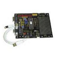
BOARD DEMO PICDEM USB
Manufacturer
Microchip Technology
Datasheet
1.DM163010.pdf
(80 pages)
Specifications of DM163010
Processor To Be Evaluated
PlC16C745/765
Interface Type
USB
Lead Free Status / RoHS Status
Lead free / RoHS Compliant
Lead Free Status / RoHS Status
Lead free / RoHS Compliant, Lead free / RoHS Compliant


©
2001 Microchip Technology Inc.
2.2.5
2.2.6
2.2.7
Keyboard
The PS/2 keyboard data report format is summarized for every key in
Mouse
Table 2.2 details a typical PS/2 mouse data format.
Table 2.2: PS/2 Mouse Data Report Format
Hardware Implementation
A PS/2 port is a 6-pin DIN, but only four pins are used (see Appendix A for
Appendix B. Make codes are the byte or bytes that the PS/2 keyboard sends
to the host when a certain key is pressed. Break codes are the bytes that the
PS/2 keyboard sends when the user releases a key. If the user does not
release a specific key for several hundreds of a millisecond, the make code
will be sent repeatedly until the user releases the key. At this point, the break
code is sent. The Translation to USB, Section 2.2.11, details how the
firmware converts PS/2 keycodes to USB keycodes.
pinout.) The pins are power, ground, clock and data. The clock pin is con-
nected to RC0, while the data pin is connected to RC1. A PS/2 device clocks
the host even when it is receiving data. By attaching the data pin to RC1, a
START bit will interrupt the PICmicro MCU through a Capture/Compare/PWM
(CCP) event. Refer to the PIC16C7XX data sheet for details on CCP. Power
and ground are directly tied to V
desired, the power pins would be driven via switches from other I/O pins.
Byte
3
2
1
Note:
The PS/2 keycodes shown in Appendix B do not apply to all PS/2
keyboards. Several code sets have been used through the years.
However, this code set is the most common.
Bit
7
6-1
0
7
6-1
0
7
6
5
4
3
2
1
0
Description
MSB of Y Data
Y Data
LSB of Y Data
MSB of X Data
X Data
LSB of X Data
Y Data Overflow, 1 = overflow
X Data Overflow, 1 = overflow
Y Data Sign, 1 = negative
X Data Sign, 1 = negative
Reserved
Reserved
Right Button Status, 1 = pressed
Left Button Status, 1 = pressed
USB Demonstration Code
DD
and V
SS
. If power management were
DS41174A-page 19
Related parts for DM163010
Image
Part Number
Description
Manufacturer
Datasheet
Request
R

Part Number:
Description:
Manufacturer:
Microchip Technology Inc.
Datasheet:
Part Number:
Description:
Manufacturer:
Microchip Technology Inc.
Datasheet:
Part Number:
Description:
Manufacturer:
Microchip Technology Inc.
Datasheet:
Part Number:
Description:
Manufacturer:
Microchip Technology Inc.
Datasheet:
Part Number:
Description:
Manufacturer:
Microchip Technology Inc.
Datasheet:
Part Number:
Description:
Manufacturer:
Microchip Technology Inc.
Datasheet:
Part Number:
Description:
Manufacturer:
Microchip Technology Inc.
Datasheet:
Part Number:
Description:
Manufacturer:
Microchip Technology Inc.
Datasheet: