ECLSOIC8EVB ON Semiconductor, ECLSOIC8EVB Datasheet - Page 18
ECLSOIC8EVB
Manufacturer Part Number
ECLSOIC8EVB
Description
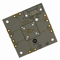
BOARD EVALUATION HI FREQ 8-SOIC
Manufacturer
ON Semiconductor
Datasheet
1.ECLSOIC8EVB.pdf
(20 pages)
Specifications of ECLSOIC8EVB
Main Purpose
Bare Evaluation Board
Lead Free Status / RoHS Status
Contains lead / RoHS non-compliant
Other names
ECLSOIC8EVB
ECLSOIC8EVBOS
ECLSOIC8EVBOS


Appendix A (Modified Configurations)
MC10EL16D/MC100EL16D
MC100LVEL16D
MC10EP16D/MC100EP16D
MC10EP16DF/MC100EP16DF
MC100EP16VAD
MC100LVEP16D
single−endedly by using the provided V
In order to drive it single−endedly, Configuration 2 needs to
be modified.
MC10EP16D/MC100EP16DT
internally. To evaluate the internal 50 W resistor of the
device, Configuration 2 needs to be modified.
MC100EP16VBD
output and being driven single−endedly using the V
utilize the feedback option and drive it single−endedly,
Configuration 2 needs to be modified.
Feedback option
Drive single−endedly
MC100EP16VCD
output with an enable pin. To utilize the feedback option and
enable option, Configuration 5 needs to be modified.
The devices listed above have the option of being driven
This device has an option of being 50 W terminated
This device has an option of single−ended feedback
This device has an option of single−ended feedback
1. Remove the 50 W chip resistor from R3.
2. Short pin 3 and pin 4 together.
1. Remove the 50 W chip resistors from R2 and R3.
2. Short R1 and R4 to V
1. Connect a SMA connector on J1
2. Remove the 50 W chip resistor from R3.
3. Short pin 3 and pin 4 together.
1. Connect a SMA connector on J1.
2. Remove the 50 W chip resistor from R3.
Option A) Short R3 and R4 trace pads.
Option B) Place a SMA connector on J4 and use
Option A) Short R1 and R4 to V
Option B) Place SMA connectors on J1 and J4.
Option A) Short R3 and R4.
Option B) Place a SMA connector on J4 and use
Or
a cable with SMA connectors to short
J3 and J4 connectors.
Or
Place shorting barrels on J1 and J4
SMA connector.
Or
a cable with SMA connectors to short
J3 and J4 connectors.
TT
(GND).
BB
TT
pin of the device.
(GND).
http://onsemi.com
ECLSOIC8EVB
BB
. To
18
MC100EP16VSD
amplitude and being driven single−endedly. In order to
utilize these options, Configuration 2 needs to be modified.
Output Swing Control
Drive Single−Endedly
MC100EP16VTD
amplitude and internal termination. In order to utilize these
options, Configuration 2 needs to be modified.
Output Swing Control
Internal Termination
MC10ELT21D/MC100EL21D
MC100EL23D
MC10ELT26D/MC100ELT26D
MC100EPT21D
MC100EPT23D
MC100EPT26D
MC100LVELT23
The TTL output data presented in the data sheet are obtained
under 500 W load resistor in parallel with 20 pF fixture
capacitance. In order to obtain comparable data as in the data
sheet, the evaluation board needs to be modified.
*Any size chip resistor can be used. The recommended size of the
chip resistor is 0402, to reduce the effect of parasitic with a 17 mil
trace width. 450 W in series with 50 W instrument resistance add up
to 500 W loaded condition.
This device has an option of varying the output swing
This device has an option of varying the output swing
1. Connect a SMA connector on J1
2. Add a decoupling capacitor between J1 and V
1. Remove the 50 W chip resistor from R3.
2. Short pin 3 and pin 4 together.
1. Connect a SMA connector on J1
2. Add a decoupling capacitor between J1 and V
1. Remove the 50 W chip resistors from R2 and R3.
2. Short R1 and R4 to V
1. Cut the output trace so that the 0402* size chip
2. Solder a 450 W chip resistor across the cut out
(0.01 mF)
(0.0 1 mF)
resistor can be placed over the cut out trace.
trace.
Option A) Short R3 and R4.
Option B) Place a SMA connector on J4 and use
Option A) Short R1 and R4 to V
Option B) Place SMA connectors on J1 and J4.
Or
a cable with SMA connectors to short
J3 and J4 connectors.
Or
Place shorting barrels on J1 and J4
SMA connector.
TT
(GND)
TT
(GND).
CC
CC
Related parts for ECLSOIC8EVB
Image
Part Number
Description
Manufacturer
Datasheet
Request
R

Part Number:
Description:
ON Semiconductor [VOLTAGE REGULATOR]
Manufacturer:
ON Semiconductor
Datasheet:
Part Number:
Description:
357-036-542-201 CARDEDGE 36POS DL .156 BLK LOPRO
Manufacturer:
ON Semiconductor
Datasheet:
Part Number:
Description:
357-036-542-201 CARDEDGE 36POS DL .156 BLK LOPRO
Manufacturer:
ON Semiconductor
Datasheet:
Part Number:
Description:
357-036-542-201 CARDEDGE 36POS DL .156 BLK LOPRO
Manufacturer:
ON Semiconductor
Datasheet:
Part Number:
Description:
357-036-542-201 CARDEDGE 36POS DL .156 BLK LOPRO
Manufacturer:
ON Semiconductor
Datasheet:
Part Number:
Description:
357-036-542-201 CARDEDGE 36POS DL .156 BLK LOPRO
Manufacturer:
ON Semiconductor
Datasheet:
Part Number:
Description:
357-036-542-201 CARDEDGE 36POS DL .156 BLK LOPRO
Manufacturer:
ON Semiconductor
Datasheet:
Part Number:
Description:
357-036-542-201 CARDEDGE 36POS DL .156 BLK LOPRO
Manufacturer:
ON Semiconductor
Datasheet:
Part Number:
Description:
357-036-542-201 CARDEDGE 36POS DL .156 BLK LOPRO
Manufacturer:
ON Semiconductor
Datasheet:
Part Number:
Description:
357-036-542-201 CARDEDGE 36POS DL .156 BLK LOPRO
Manufacturer:
ON Semiconductor
Datasheet:
Part Number:
Description:
357-036-542-201 CARDEDGE 36POS DL .156 BLK LOPRO
Manufacturer:
ON Semiconductor
Datasheet:
Part Number:
Description:
Manufacturer:
ON Semiconductor
Datasheet:
Part Number:
Description:
Manufacturer:
ON Semiconductor
Datasheet:
Part Number:
Description:
Manufacturer:
ON Semiconductor
Datasheet: