ECLSOIC8EVB ON Semiconductor, ECLSOIC8EVB Datasheet - Page 16
ECLSOIC8EVB
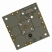
Manufacturer Part Number
ECLSOIC8EVB
Description
BOARD EVALUATION HI FREQ 8-SOIC
Manufacturer
ON Semiconductor
Datasheet
1.ECLSOIC8EVB.pdf
(20 pages)
Specifications of ECLSOIC8EVB
Main Purpose
Bare Evaluation Board
Lead Free Status / RoHS Status
Contains lead / RoHS non-compliant
Other names
ECLSOIC8EVB
ECLSOIC8EVBOS
ECLSOIC8EVBOS


LAB SETUP
Table 15. Power Supply Levels
Signal Generator
1. Connect appropriate power supplies to V
Power Supply
Differential
and GND.
For standard ECL lab setup and test, a split (dual)
power supply is required enabling the 50 W
internal impedance in the oscilloscope to be used
as a termination of the ECL signals (V
– 2.0 V, in split power supply setup, V
system ground, V
–1.3 V; see Table 15).
5.0 V
3.3 V
2.5 V
TRIGGER
OUT1
OUT1
OUT2
OUT2
CC
2.0 V
2.0 V
2.0 V
is 2.0 V, and V
V
Figure 15. Example of Standard Lab Setup (Configuration 1)
CC
J2
J3
−3.0 V
−1.3 V
−0.5 V
V
EE
EE
TT
TT
is –3.0 V or
CC
is the
= V
J4
J1
0.0 V
0.0 V
0.0 V
GND
, V
http://onsemi.com
ECLSOIC8EVB
CC
EE
DUT
V
V
CC
EE
,
Power Supply
Power Supply
16
The power supply for voltage level translating device need
slight modification as indicated in Table 16.
NOTE: The test measurement device must contain 50 W
Table 16. Power Supply Levels for Translators
PECL Translators
GND
GND
2. Connect a signal generator to the input SMA
3. Connect a test measurement device on the device
connectors. Setup input signal according to the
device data sheet.
output SMA connectors.
J7
J6
termination.
3.3 V / 5.0 V
V
CC
Channel 1
Channel 2
TRIGGER
Test Measuring
Equipment
0.0 V
V
EE
GND
0.0 V
Related parts for ECLSOIC8EVB
Image
Part Number
Description
Manufacturer
Datasheet
Request
R

Part Number:
Description:
ON Semiconductor [VOLTAGE REGULATOR]
Manufacturer:
ON Semiconductor
Datasheet:
Part Number:
Description:
357-036-542-201 CARDEDGE 36POS DL .156 BLK LOPRO
Manufacturer:
ON Semiconductor
Datasheet:
Part Number:
Description:
357-036-542-201 CARDEDGE 36POS DL .156 BLK LOPRO
Manufacturer:
ON Semiconductor
Datasheet:
Part Number:
Description:
357-036-542-201 CARDEDGE 36POS DL .156 BLK LOPRO
Manufacturer:
ON Semiconductor
Datasheet:
Part Number:
Description:
357-036-542-201 CARDEDGE 36POS DL .156 BLK LOPRO
Manufacturer:
ON Semiconductor
Datasheet:
Part Number:
Description:
357-036-542-201 CARDEDGE 36POS DL .156 BLK LOPRO
Manufacturer:
ON Semiconductor
Datasheet:
Part Number:
Description:
357-036-542-201 CARDEDGE 36POS DL .156 BLK LOPRO
Manufacturer:
ON Semiconductor
Datasheet:
Part Number:
Description:
357-036-542-201 CARDEDGE 36POS DL .156 BLK LOPRO
Manufacturer:
ON Semiconductor
Datasheet:
Part Number:
Description:
357-036-542-201 CARDEDGE 36POS DL .156 BLK LOPRO
Manufacturer:
ON Semiconductor
Datasheet:
Part Number:
Description:
357-036-542-201 CARDEDGE 36POS DL .156 BLK LOPRO
Manufacturer:
ON Semiconductor
Datasheet:
Part Number:
Description:
357-036-542-201 CARDEDGE 36POS DL .156 BLK LOPRO
Manufacturer:
ON Semiconductor
Datasheet:
Part Number:
Description:
Manufacturer:
ON Semiconductor
Datasheet:
Part Number:
Description:
Manufacturer:
ON Semiconductor
Datasheet:
Part Number:
Description:
Manufacturer:
ON Semiconductor
Datasheet: