USBMULTILINKBDME Freescale Semiconductor, USBMULTILINKBDME Datasheet - Page 4
USBMULTILINKBDME
Manufacturer Part Number
USBMULTILINKBDME
Description
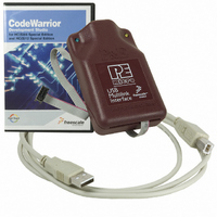
PROGRAMMER MULTILINK HCS08/HCS12
Manufacturer
Freescale Semiconductor
Series
USB Multilinkr
Type
In Circuit Debuggerr
Specifications of USBMULTILINKBDME
Contents
Module and Misc Hardware
Positions/sockets
1
Description/function
USB HCS08/HCS12 BDM Multilink - In-circuit Debugger/Programmer
Core Architecture
Coldfire, HCS08, RS08
Core Sub-architecture
Coldfire V1, HCS08, RS08
Ic Product Type
In-Circuit Debugger / Programmer
Rohs Compliant
Yes
For Use With/related Products
HCS08, HC(S)12(X), RS08, ColdFire V1
Lead Free Status / RoHS Status
Lead free / RoHS Compliant
Available stocks
Company
Part Number
Manufacturer
Quantity
Price
Company:

Part Number:
USBMULTILINKBDME
Manufacturer:
INFINEON
Quantity:
2 626
Part Number:
USBMULTILINKBDME
Manufacturer:
FREESCALE
Quantity:
20 000


Before disconnecting the setup, turn the target power off.
7.0 Startup Reset Sequence
In order to use the Background Debug Mode of the microcontroller, it is initialized into debug mode via a
reset sequence.
This is accomplished by P&E’s software via the following reset sequence:
RST
8.0 Interface Libraries
One of the products P&E produces is a set of interface libraries which allows the user to directly control the
USB HCS08/HCS12 Multilink from any Windows Development Environment which can interact with a
DLL. The interface libraries come with examples for controlling the Multilink interface from Microsoft
Visual C as well as Borland Delphi. Details of the libraries for the RS08 may be found at
Product
the libraries for the HC12 and HCS12 may be found at
9.0 Firmware Updates
The latest version of the firmware for the Multilink interface is included in P&E software development kits.
When the debugger or programmer is run, if it detects that the Multilink interface firmware needs to be
updated, it will ask the user’s permission to do this. If granted, the update happens automatically.
Alternately, the latest version of the firmware may be downloaded from the “Firmware Updates” section of
the “Support Center” located at http://www.pemicro.com.
BKGD
2) Connect the Multilink to the target via its ribbon cable. Make sure that the ribbon cable is plugged
3) Connect the Multilink to the PC via a USB extension cable. The Blue LED on the Multilink should
4) Turn the target power on. The Yellow LED on the Multilink should become lit.
into the target with the proper orientation. PIN 1 is denoted by the red stripe running down the
ribbon cable.
become lit.
a) Initially the BKGD (pin-1) and Reset (pin-4) are pulled low.
b) After 5 milliseconds, the RESET (pin-4) goes high.
c) After 10 milliseconds, the BKGD (pin-1) goes high.
d) Wait for 20 milliseconds, followed by activities on BKGD (pin-1).
Page. Details of the libraries for the HCS08 may be found at
5msec
10msec
20msec
P&E's HC(S)12 Product
P&E's HCS08 Product
Page.
P&E's RS08
Page. Details of
Related parts for USBMULTILINKBDME
Image
Part Number
Description
Manufacturer
Datasheet
Request
R

Part Number:
Description:
Manufacturer:
Freescale Semiconductor, Inc
Datasheet:
Part Number:
Description:
Manufacturer:
Freescale Semiconductor, Inc
Datasheet:
Part Number:
Description:
Manufacturer:
Freescale Semiconductor, Inc
Datasheet:
Part Number:
Description:
Manufacturer:
Freescale Semiconductor, Inc
Datasheet:
Part Number:
Description:
Manufacturer:
Freescale Semiconductor, Inc
Datasheet:
Part Number:
Description:
Manufacturer:
Freescale Semiconductor, Inc
Datasheet:
Part Number:
Description:
Manufacturer:
Freescale Semiconductor, Inc
Datasheet:
Part Number:
Description:
Manufacturer:
Freescale Semiconductor, Inc
Datasheet:
Part Number:
Description:
Manufacturer:
Freescale Semiconductor, Inc
Datasheet:
Part Number:
Description:
Manufacturer:
Freescale Semiconductor, Inc
Datasheet:
Part Number:
Description:
Manufacturer:
Freescale Semiconductor, Inc
Datasheet:
Part Number:
Description:
Manufacturer:
Freescale Semiconductor, Inc
Datasheet:
Part Number:
Description:
Manufacturer:
Freescale Semiconductor, Inc
Datasheet:
Part Number:
Description:
Manufacturer:
Freescale Semiconductor, Inc
Datasheet:
Part Number:
Description:
Manufacturer:
Freescale Semiconductor, Inc
Datasheet: