USBMULTILINKBDME Freescale Semiconductor, USBMULTILINKBDME Datasheet - Page 2
USBMULTILINKBDME
Manufacturer Part Number
USBMULTILINKBDME
Description
PROGRAMMER MULTILINK HCS08/HCS12
Manufacturer
Freescale Semiconductor
Series
USB Multilinkr
Type
In Circuit Debuggerr
Specifications of USBMULTILINKBDME
Contents
Module and Misc Hardware
Positions/sockets
1
Description/function
USB HCS08/HCS12 BDM Multilink - In-circuit Debugger/Programmer
Core Architecture
Coldfire, HCS08, RS08
Core Sub-architecture
Coldfire V1, HCS08, RS08
Ic Product Type
In-Circuit Debugger / Programmer
Rohs Compliant
Yes
For Use With/related Products
HCS08, HC(S)12(X), RS08, ColdFire V1
Lead Free Status / RoHS Status
Lead free / RoHS Compliant
Available stocks
Company
Part Number
Manufacturer
Quantity
Price
Company:

Part Number:
USBMULTILINKBDME
Manufacturer:
INFINEON
Quantity:
2 626
Part Number:
USBMULTILINKBDME
Manufacturer:
FREESCALE
Quantity:
20 000


The pin-outs of the connector as specified by Freescale are:
2.0 Usage of the USB HCS08/HCS12 Multilink Interface
The USB HCS08/HCS12 MULTILINK can communicate with an RS08, HCS08, HC12, or HCS12 processor
whose bus frequency is up to 35 MHz. P&E’s software packages will automatically detect the proper
communications rate to establish a connection with the target. For HC12/HCS12 devices, the BDM
communications speed may be set (instead of being auto-detected) by setting the value of the
IO_DELAY_CNT variable. The proper IO_DELAY_CNT may be calculated by the equation:
IO_DELAY_CNT = (120000000 / Fbus) – 1
Fbus is the bus frequency in hertz. The RS08 and HCS08 frequency is always detected automatically.
The Multilink interface will work with targets whose processor power supply is in the range of 1.6V to 5.25V.
The Multilink interface derives its power from the USB port and as such draws less than 1mA from the
target.
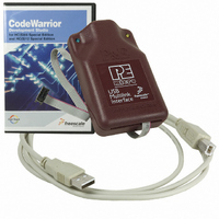
The USB HCS08/HCS12 Multilink has a female type B USB connector. Use a Type A to Type B USB
extension cable to connect the interface to the PC.
The USB HCS08/HCS12 Multilink is a high power USB device. If a USB HUB is used, it must be a self-
powered hub (i.e. with a power supply). By default, the USB protocol used is 2.0.
There are two LEDs, which protrude through the housing of the USB HCS08/HCS12 Multilink interface.
The Blue LED indicates that the Multilink interface is powered and running. The Yellow LED indicates that
target power has been detected.
The 6-pin ribbon cable, which allows connection to the target debug connector, is fixed within the Multilink
housing. PIN 1 is denoted by the red stripe running down the ribbon cable.
3.0 Driver Installation on Windows XP/2000
Before connecting the USB HCS08/HCS12 Multilink to the PC, the appropriate drivers need to be installed
on the PC. The drivers are automatically installed when installing any of P&E’s RS08/HCS08/HC12/HCS12
development packages built after January 1, 2005. A copy of the driver installation program may also be
downloaded from the “Downloads” section of P&E’s “Support Center” located at http://www.pemicro.com.
When the cable is plugged in, the operating system should indicate that it has found a driver for the attached
“USB Multilink 2.0”. Follow the instructions in the “Found New Hardware Wizard” dialog for having
Windows automatically install the driver.
Related parts for USBMULTILINKBDME
Image
Part Number
Description
Manufacturer
Datasheet
Request
R

Part Number:
Description:
Manufacturer:
Freescale Semiconductor, Inc
Datasheet:
Part Number:
Description:
Manufacturer:
Freescale Semiconductor, Inc
Datasheet:
Part Number:
Description:
Manufacturer:
Freescale Semiconductor, Inc
Datasheet:
Part Number:
Description:
Manufacturer:
Freescale Semiconductor, Inc
Datasheet:
Part Number:
Description:
Manufacturer:
Freescale Semiconductor, Inc
Datasheet:
Part Number:
Description:
Manufacturer:
Freescale Semiconductor, Inc
Datasheet:
Part Number:
Description:
Manufacturer:
Freescale Semiconductor, Inc
Datasheet:
Part Number:
Description:
Manufacturer:
Freescale Semiconductor, Inc
Datasheet:
Part Number:
Description:
Manufacturer:
Freescale Semiconductor, Inc
Datasheet:
Part Number:
Description:
Manufacturer:
Freescale Semiconductor, Inc
Datasheet:
Part Number:
Description:
Manufacturer:
Freescale Semiconductor, Inc
Datasheet:
Part Number:
Description:
Manufacturer:
Freescale Semiconductor, Inc
Datasheet:
Part Number:
Description:
Manufacturer:
Freescale Semiconductor, Inc
Datasheet:
Part Number:
Description:
Manufacturer:
Freescale Semiconductor, Inc
Datasheet:
Part Number:
Description:
Manufacturer:
Freescale Semiconductor, Inc
Datasheet: