ST-LINK STMicroelectronics, ST-LINK Datasheet - Page 13
ST-LINK
Manufacturer Part Number
ST-LINK
Description
DEBUGGER/PROGRAMMER STM8 STM32
Manufacturer
STMicroelectronics
Type
In-Circuit Debugger/Programmerr
Datasheet
1.ST-LINK.pdf
(22 pages)
Specifications of ST-LINK
Contents
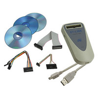
Module, Cables
Positions/sockets
1
Description/function
In-Circuit Programmer, Debugger
Core Architecture
ARM, STM8
Core Sub-architecture
Cortex - M3, STM8
Ic Product Type
In-Circuit Debugger / Programmer
For Use With/related Products
STM8, STM32
Lead Free Status / RoHS Status
Lead free / RoHS Compliant
Other names
497-10484
ST-LINK
ST-LINK
Available stocks
Company
Part Number
Manufacturer
Quantity
Price

Company:
Part Number:
ST-LINK/V2
Manufacturer:
P&S
Quantity:
1 700
Part Number:
ST-LINK/V2
Manufacturer:
ST
Quantity:
20 000
Part Number:
ST-LINK/V2-ISOL
Manufacturer:
ST
Quantity:
20 000


UM0892
●
●
Figure 13. Option Bytes dialog box
For more details, please refer to the Option Bytes section in the Flash programming manual
available from www.st.com.
–
User data storage option bytes: Contains two bytes for user storage. These two
option bytes are not available in the STM32 F-2 and STM32 L-1 series.
Write Protection: Depending on the device, Flash sectors are grouped by a defined
number of sectors. You can modify the write protection of each Flash sector group here.
BFB2: If not checked, and if the boot pins are set to make the device boot from
user Flash at startup, the device boots from Flash memory bank 2, otherwise it
boots from Flash memory bank 1. This option is enabled only when connected to a
device containing two Flash banks.
Doc ID 16987 Rev 5
STM32 ST-LINK utility features
13/22
Related parts for ST-LINK
Image
Part Number
Description
Manufacturer
Datasheet
Request
R

Part Number:
Description:
STMicroelectronics [RIPPLE-CARRY BINARY COUNTER/DIVIDERS]
Manufacturer:
STMicroelectronics
Datasheet:
Part Number:
Description:
STMicroelectronics [LIQUID-CRYSTAL DISPLAY DRIVERS]
Manufacturer:
STMicroelectronics
Datasheet:

Part Number:
Description:
BOARD EVAL FOR MEMS SENSORS
Manufacturer:
STMicroelectronics
Datasheet:
Part Number:
Description:
NPN TRANSISTOR POWER MODULE
Manufacturer:
STMicroelectronics
Datasheet:
Part Number:
Description:
TURBOSWITCH ULTRA-FAST HIGH VOLTAGE DIODE
Manufacturer:
STMicroelectronics
Datasheet:
Part Number:
Description:
Manufacturer:
STMicroelectronics
Datasheet:
Part Number:
Description:
DIODE / SCR MODULE
Manufacturer:
STMicroelectronics
Datasheet:
Part Number:
Description:
DIODE / SCR MODULE
Manufacturer:
STMicroelectronics
Datasheet:
Part Number:
Description:
Search -----> STE16N100
Manufacturer:
STMicroelectronics
Datasheet:
Part Number:
Description:
Search ---> STE53NA50
Manufacturer:
STMicroelectronics
Datasheet:
Part Number:
Description:
NPN Transistor Power Module
Manufacturer:
STMicroelectronics
Datasheet:
Part Number:
Description:
DIODE / SCR MODULE
Manufacturer:
STMicroelectronics
Datasheet: