ST-LINK STMicroelectronics, ST-LINK Datasheet - Page 12
ST-LINK
Manufacturer Part Number
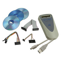
ST-LINK
Description
DEBUGGER/PROGRAMMER STM8 STM32
Manufacturer
STMicroelectronics
Type
In-Circuit Debugger/Programmerr
Datasheet
1.ST-LINK.pdf
(22 pages)
Specifications of ST-LINK
Contents
Module, Cables
Positions/sockets
1
Description/function
In-Circuit Programmer, Debugger
Core Architecture
ARM, STM8
Core Sub-architecture
Cortex - M3, STM8
Ic Product Type
In-Circuit Debugger / Programmer
For Use With/related Products
STM8, STM32
Lead Free Status / RoHS Status
Lead free / RoHS Compliant
Other names
497-10484
ST-LINK
ST-LINK
Available stocks
Company
Part Number
Manufacturer
Quantity
Price

Company:
Part Number:
ST-LINK/V2
Manufacturer:
P&S
Quantity:
1 700
Part Number:
ST-LINK/V2
Manufacturer:
ST
Quantity:
20 000
Part Number:
ST-LINK/V2-ISOL
Manufacturer:
ST
Quantity:
20 000


STM32 ST-LINK utility features
3.5
12/22
Figure 12. Device programming dialog box (verification)
Option bytes configuration
The STM32 ST-LINK utility can configure all the option bytes via the Option Bytes dialog
box shown in
The Option Bytes dialog box contains the following sections:
●
●
●
Read Out Protection: Modifies the read protection state of the Flash memory.
For STM32 F-2 and STM32 L-1 series, read protection levels are available:
–
–
–
For the other devices, the read protection can only be enabled or disabled.
BOR Level: Brownout reset level. This list contains the supply level threshold that
activates/releases the brownout reset. This option is enabled only when connected to
an ultralow an STM32 F-2 or STM32 L-1 device.
For STM32 L-1 series, 5 programmable VBOR thresholds can be selected:
–
–
–
–
–
For STM32 F-2 series, 4 programmable VBOR thresholds can be selected:
–
–
–
–
User Configuration option byte:
–
–
–
Level 0: no read protection
Level 1: memory read protection enabled
Level 2: memory read protection enabled and all debug features disabled
BOR LEVEL 1: Reset threshold level for 1.69 to 1.8 V voltage range
BOR LEVEL 2: Reset threshold level for 1.94 to 2.1 V voltage range
BOR LEVEL 3: Reset threshold level for 2.3 to 2.49 V voltage range
BOR LEVEL 4: Reset threshold level for 2.54 to 2.74 V voltage range
BOR LEVEL 5: Reset threshold level for 2.77 to 3.0 V voltage range
BOR LEVEL 3:
BOR LEVEL 2:
BOR LEVEL 1:
BOR off:
WDG_SW : If checked, watchdog is enabled by software - otherwise it is
automatically enabled at power-on.
nRST_STOP: If not checked, reset is generated when entering Standby mode
(1.8V domain powered-off). If checked, no reset is generated when entering
Standby mode.
nRST_STDBY: if not checked, reset is generated when entering Stop mode (all
clocks are stopped). If checked, no reset is generated when entering Stop mode.
Figure 13
which is accessed by Target | Option Bytes....
Supply voltage rangess from 2.70 to 3.60 V
Supply voltage ranges from 2.40 to 2.70 V
Supply voltage ranges from 2.10 to 2.40 V
Supply voltage ranges from 1.62 to 2.10 V
Doc ID 16987 Rev 5
UM0892
Related parts for ST-LINK
Image
Part Number
Description
Manufacturer
Datasheet
Request
R

Part Number:
Description:
STMicroelectronics [RIPPLE-CARRY BINARY COUNTER/DIVIDERS]
Manufacturer:
STMicroelectronics
Datasheet:
Part Number:
Description:
STMicroelectronics [LIQUID-CRYSTAL DISPLAY DRIVERS]
Manufacturer:
STMicroelectronics
Datasheet:

Part Number:
Description:
BOARD EVAL FOR MEMS SENSORS
Manufacturer:
STMicroelectronics
Datasheet:
Part Number:
Description:
NPN TRANSISTOR POWER MODULE
Manufacturer:
STMicroelectronics
Datasheet:
Part Number:
Description:
TURBOSWITCH ULTRA-FAST HIGH VOLTAGE DIODE
Manufacturer:
STMicroelectronics
Datasheet:
Part Number:
Description:
Manufacturer:
STMicroelectronics
Datasheet:
Part Number:
Description:
DIODE / SCR MODULE
Manufacturer:
STMicroelectronics
Datasheet:
Part Number:
Description:
DIODE / SCR MODULE
Manufacturer:
STMicroelectronics
Datasheet:
Part Number:
Description:
Search -----> STE16N100
Manufacturer:
STMicroelectronics
Datasheet:
Part Number:
Description:
Search ---> STE53NA50
Manufacturer:
STMicroelectronics
Datasheet:
Part Number:
Description:
NPN Transistor Power Module
Manufacturer:
STMicroelectronics
Datasheet:
Part Number:
Description:
DIODE / SCR MODULE
Manufacturer:
STMicroelectronics
Datasheet: